I'm working on an application using a three axis magnetometer from Memsic (MMC5983). This supports I2C and SPI but for application specific reasons I need to use SPI.
I've spent the past couple of days trying to work out why I cant get a coherent response from the chip and today finally tried using an Pro Micro 3v3 (Sparkfun) instead of the Due which I had laying around and to my surprise everything started working.
Upon comparison using a scope it appears that on the Pro Micro the default state of MOSI is low, whereas on the Due it's high. No other differences that I can work out. Despite the MMCs data sheets suggestion that it shouldn't make a difference it appears that having MOSI high when CS goes low causes some anomalies.
I cannot for the life of me work out how to keep MOSI low on the Due. According to the SAM3X8E datasheet it doesn't appear that the line should be driven specifically high at the end of a write command (unless I missed something).
Does anyone have any ideas regarding this? Any help is appreciated.
As a workaround, you could manually set the MOSI pin to Low before CS goes LOW (set the MOSI pin to the GPIO, set it to LOW, then set the pin to SPI peripheral again).
As a workaround, you could manually set the MOSI pin to Low before CS goes LOW (set the MOSI pin to the GPIO, set it to LOW, then set the pin to SPI peripheral again).
Thanks for the input!
I'll give this a go on Monday, don't have the hardware at the moment. Ideally I would prefer not to be loosing the clock cycles to switching around the pins but it should at least show if the MMC has some strange quirks.
Unfortunately I was unable to get it to work with the suggested fix. Seems to be due to some noise rather than the state of the MOSI line, other than that - not so sure. For anyone interested in how to implement the suggested fix I just added these lines:
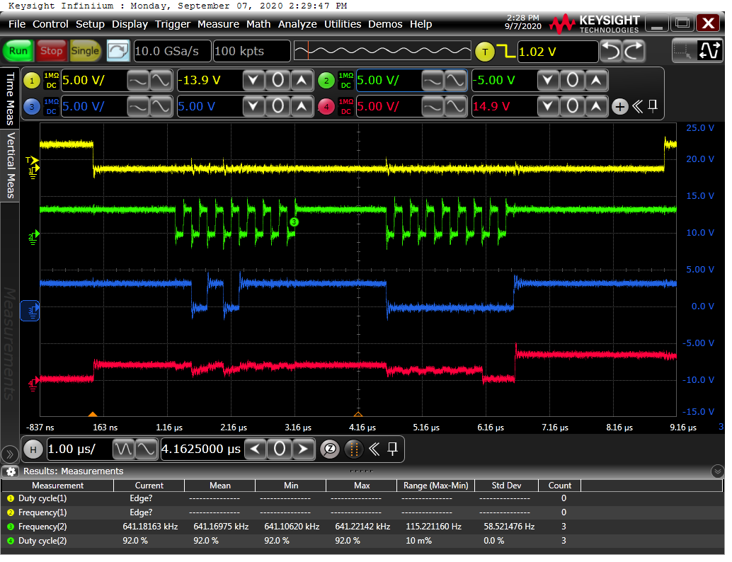
If anyone has any ideas then I have attached captures from when on the scope. One is from a ProMicro then other from a Due. Both should be the same clock frequency:
Yellow = Chip Select
Green = Clock
Blue = MOSI
Red = MISO
Expected response is 0x30 (which is correct for pro micro).
I use two SPI units with the Due to control two stepper motors. Not had an issue but the SPI implementation is done for me by the library.
Code excepts in case it helps. #include <SPI.h> #include <HighPowerStepperDriver.h>
void InitStepperDriver(HighPowerStepperDriver StepperDriver, uint16_t MotorMilliamps)
{
// Reset the driver to its default settings and clear latched status
StepperDriver.resetSettings();
// Select auto mixed decay. TI's DRV8711 documentation recommends this mode
// for most applications, and we find that it usually works well.
StepperDriver.setDecayMode(HPSDDecayMode::AutoMixed);
// Set the current limit. You should change the number here to an appropriate
// value for your particular system.
StepperDriver.setCurrentMilliamps36v4(MotorMilliamps);
// Set the number of microsteps that correspond to one full step.
StepperDriver.setStepMode(HPSDStepMode::MicroStep256);
// Enable the motor outputs.
StepperDriver.enableDriver();
}