CrossRoads:
TM2313 datasheet
Can you translate this? I see some stuff that talks about the MCU and the data needed.
Hi! I actually used google translator and it translates all very well, I can share some translations talking about how to communicate with MCU:
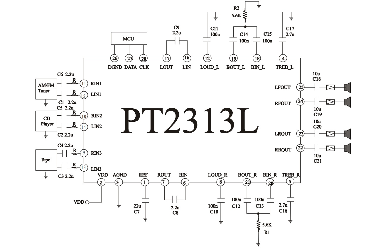
TM2313 is a three-pair input four-channel output digital control audio processing chip. The chip uses deep sub-micron CMOS
Process technology manufacturing, the chip contains volume, bass, treble, channel equalization, pre/post attenuation, and loudness processing;
In one chip, multiple selectable gain input terminals are assembled, with few peripheral circuit components, and better performance and reliability.
All functions are driven and realized by PC bus programming. TM2313 adopts SOP28/DIP28 package. Pin arrangement
The principle and application circuit are simple, which is very conducive to the layout of the circuit board and cost saving.
2. Features
- Manufactured using CMOS technology;
- Few peripheral circuit components;
- Treble and bass control;
- With loudness function;
- 3 sets of stereo input, input amplification gain can be adjusted;
- It can reduce the noise between the input and output terminals, the system and the equalizer;
- It can perform channel equalization and attenuation processing control for 4 independent speakers;
- Independent mute function;
- Volume control: 1.25dB/step;
- Low distortion;
- Low noise and DC drift;
- Via serial I2
C bus microprocessor interface to control;
- SOP28/DIP28 package
- Compatible with TDA7313, PT2313
- Application:
- Car audio;
- Hi-Fi sound system;
PIN DESCRIPTION:
Pin name|| I/O|| Function description ||Pin number
REF|| -|| Reference voltage (1/2VDD)|| 1
VDD|| -|| Power supply|| 2
AGND|| -|| Analog ground ||3
TREB_L|| I|| 4
TREB_R ||I|| Left and right channel treble control||Pin 5
RIN|| I|| Right channel audio processor input terminal||Pin 6
ROUT ||O|| The right channel audio source is amplified by the selected gain and output||Pin 7
LOUD_R|| I|| Right channel loudness control||Pin 8
Right channel audio source 1/2/3 input:
RIN3|| I||pin 9
RIN2 ||I|Pin| 10
RIN1 ||I||Pin 11
LOUD_L||I|| Left channel loudness control||Pin 12
Left channel audio source 1/2/3 input:
LIN3|| I ||13
LIN2|| I ||14
LIN1|| I ||15
LIN|| I ||Left channel audio processor input terminal||Pin 16
LOUT|| O ||The left channel audio source is amplified by the selected gain and output||Pin 17
BIN_L|| I ||18
BOUT_L|| O ||Left channel bass processing input/output||Pin 19
BIN_R|| I ||20
BOUT_R|| O ||Right channel bass processing input/output||Pin 21
RROUT|| O ||Rear speaker right channel output ||Pin 22
LROUT|| O ||Rear speaker left channel output||Pin 23
RFOUT ||O ||Front speaker right channel output ||Pin 24
LFOUT|| O|| Front speaker left channel output ||Pin 25
DGND||-||Digital Ground||Pin 26
DATA|| I ||I2C data input pin||Pin 27
CLK|| I ||I2C clock||pin 28
I2C:
Function description:
- I2C bus interface
The data of the microprocessor communicates with the TM2313 through a two-wire I2C bus interface. The two wires are SDA and SCL respectively.
(Need to pull up resistor to VDD).
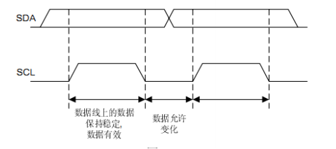
- Data stability requirements
When SCL is high, the signal on SDA must remain unchanged; only the clock signal on SCL is low
Only when the signal on SDA can be changed.
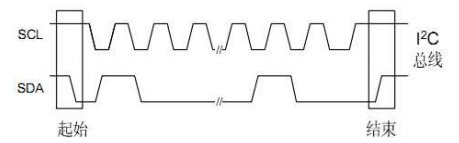
According to the start and end conditions of the transmission
Start condition: when SCL is high, SDA changes from high to low;
End condition: when SCL is high, SDA changes from low to high;
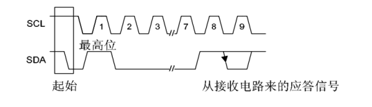
Byte format
The byte transmitted on SDA must contain 8 bits; each byte must be transmitted with an acknowledge signal bit;
High bit priority transmission.
Acknowledgment signal bit (ACK)
When transmitting the response signal, the host control signal pulls the SDA line high through the pull-up resistor; and the addressed chip should
When answering, pull the SDA line directly low and keep it for one bit. After receiving a byte correctly, the chip will send a response
Signal; that is, at the ninth clock pulse, SDA is set to low level; the control part generates an end command to suspend the transmission of data
according to.
Transmission without response signal
In the application, the host can cancel the detection of the response signal and adopt a simpler transmission method: do not detect the response signal
Only after waiting for one bit, new data can be transmitted; this method cannot guarantee the correctness of the transmission, and also
Reduce the anti-interference ability.
7. Interface protocol:
- Start signal
- Address byte, including TM2313 address (the eighth bit must be 0);
- Data sequence
- End conditions
(***A response signal is generated every time a byte is transmitted.)
- Instructions
Device address:
Control byte format description:

Data control bit detailed description
-
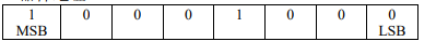
Volume control command:
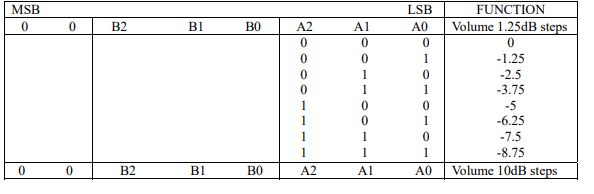
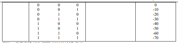
For example: the volume attenuation is 45db, it is represented by "00100100".
-
Speaker attenuation command:
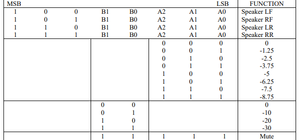
For example: the right channel of the front speaker has an attenuation of 25db, which is represented by "10110100".
-
Input switch/loudness control/input gain command:

For example: Choose stereo channel 2 to input a gain of 7.5db, and turn on the loudness, it will be represented by "01001001".
Note: Stereo4 has no external pins.
-
High/bass sound quality control commands:
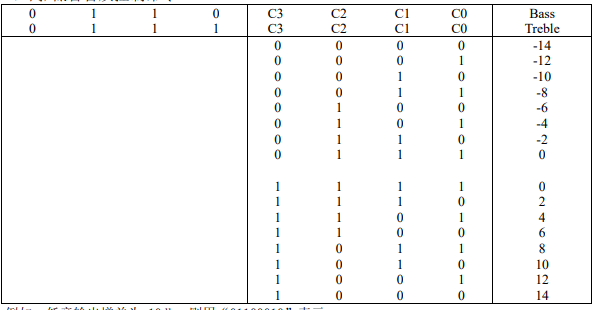
For example: if the bass output gain is -10db, it is represented by "01100010".