Buttons and other electro-mechanical inputs (introduction)

Intended audience
This tutorial is intended for people who have mastered the basics of electronics and C/C++ programming. If you are a beginner and find the concepts difficult, please review the basic examples in the Arduino IDE.
In this tutorial BUTTON will be a generic term for any kind of switch or other input device with mechanical contacts.

Introduction
A common requirement in many projects is to have push buttons, switches or other electro-mechanical devices connected as inputs to an Arduino. This tutorial shows you how to connect a button and respond reliably to changes in the button's state.

Subjects covered

Part 1

  • How to wire a push button switch to an input on the Arduino. Detect button operation and initiate actions.
  • Code examples for above.
  • Sample output on the serial monitor

Part 2

  • The reason for debouncing the signal from any device with mechanical contacts
  • Pull-up resistors, what they are and why they are required
  • Pull-up vs pull-down
  • State change detection
  • Voltage, no voltage and 0v

Part 1

Single button input
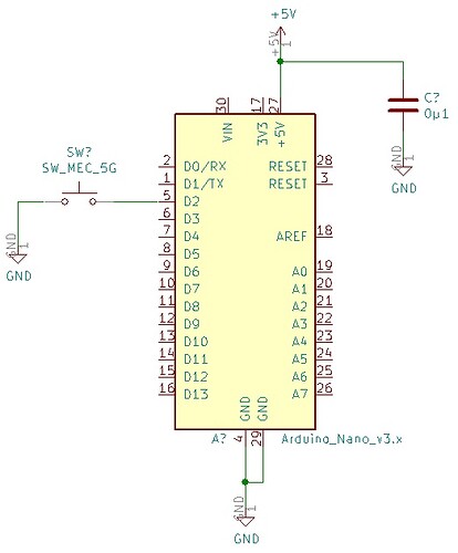
The schematic shows a single button connected to an input on an Arduino Nano. On many Arduinos digital inputs 0 and 1 are used for the serial monitor. Digital input 2 is the first free input and is used in this example.

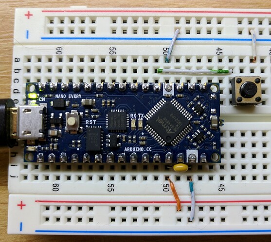
Here is what it looks like with a Nano Every on breadboard

Code for single button input to detect when the button becomes pressed

/* Simple debounce for a single push to make button wired between ground (0V) and buttonPin */
/* Tested on a Nano Every, should work on any Arduino */

const uint8_t BUTTONPIN = 2;          // Input for button. On many Arduinos pins 0 and 1 are used for serial making pin 2 the first free pin.

void setup() {
  Serial.begin(9600);                 // Start the serial monitor to see the results.
  char fileName[] = {__FILE__};
  Serial.println(fileName);           // Prints the name of the file the location this sketch is in.
  pinMode(BUTTONPIN, INPUT_PULLUP);   // Make the button pin an input with the internal pull up resistor enabled.
}

void loop() {
  Buttons();                          // Calls the function to read the button.
  // Your other code goes here, make sure it is non blocking (no delays, no loops that don't exit quickly)
}

/* This is the function that reads the state of the button, debounces it and prints to the serial monitor when it detects a press */
void Buttons() {
  #define buttonPressed LOW                             // When the button is pressed the input will be low, this is to remove the confusion this migth cause.
  uint32_t currentMillis = millis();                    // Millis times uses to debounce the button
  static uint32_t lastMillis;                           // Start of the debounce timeout
  const uint32_t BOUNCETIMEOUT = 20;                    // Debounce time in milliseconds 
  bool currentButtonState = digitalRead(BUTTONPIN);     // Reads the current state of the button and saves the result in a bool
  static bool lastButtonState;                          // Holds the previous debounced state of the button
  
  if (lastButtonState != currentButtonState) {          // Checks to see if the button has been pressed or released, at this point the button has not been debounced
    if (currentMillis - lastMillis >= BOUNCETIMEOUT) {  // Checks to see if the state of the button has been stable for at least bounceTimeout duration
      lastButtonState = currentButtonState;             // At this point the button has been debounced, so save the last state
      if (currentButtonState == buttonPressed) {        // The button might have been pressed or released, this make sure only presses are acted on, not releases
        Serial.println ("Button has been pressed");     // Here you put whatever code you want to take action when the button is pressed
      }
    }
  } else {
    lastMillis = currentMillis;                         // Saves the current value of millis in last millis so the debounce timer starts from current millis
  }
}

This is what you can expect on the serial monitor
1 Like

Part 2
Part 1 shows how to read a single button. This part explains the code and circuit.

Debouncing
You have probably heard of debouncing and are perhaps wondering what it is and why it is needed.

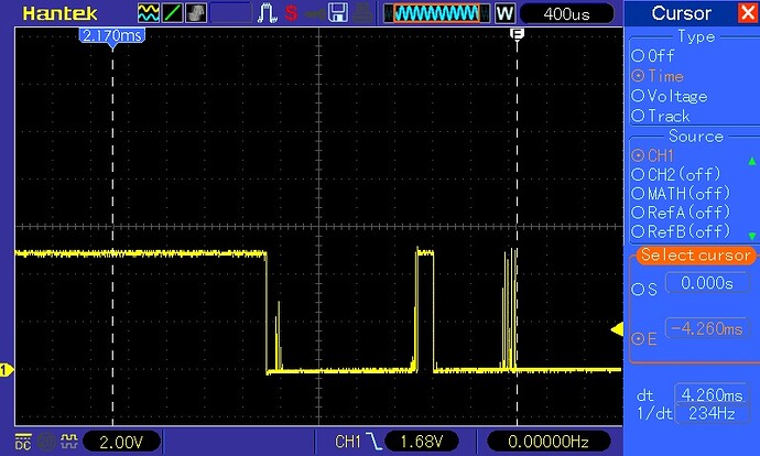
The oscilloscope trace below was taken from a single button wired as in part 1. The trace shows high and low transitions - some lasting over 4ms - before the signal settles at low. This is caused by mechanical bouncing of the button's contacts. We can use software to remove these unwanted transitions. The millis() based timer code in part 1 makes sure the bouncing has stopped before registering the button press as valid.

Input pull up or pull down
If you are new to electronics you might be wondering what pull up (or down) resistors are and why inputs need them at all.

Input pin nothing connected.jpg

The equivalent 2 MOSFET circuit in the image above is typical for micro-controller inputs. I am not saying that is the exact circuit, it probably is not, but it gives a basic idea. The input pin is connected to the gates of a pair of MOSFETs. MOSFET gates are a conductive layer close to, but insulated from, the conductive channel that carries the current in the MOSFET flowing between source and drain. This insulating layer has an extremely high resistance, so effectively the input is a small capacitor. Because of this, the input pin is essentially a well-insulated open circuit, not connected to anything.

Input pin button connected.jpg

When a button (switch) is the only thing connected to an input and the button is open, the input is said to be floating. Because of the high input resistance, whatever voltage was last applied to the input remains. If the button is connected to ground and closed, the input voltage goes to 0 volts and stays at 0 volts when the button opens.

Input pin button and pull up connected.jpg

Many micro-controllers have software enabled pull-up and/or pull-down resistors.
Floating input voltages can be removed by using these. A resistor between the input and Vcc is a pull-up resistor. A resistor between ground and the input is called a pull-down resistor. In the example above, when the button opens, a pull-up resistor would make the input go to Vcc rather than sitting at a floating 0 Volt level.
On the other hand, if our switch were between Vcc and the input, and we connected a pull-down resistor between the input and ground, an open button would be read as 0 volts and a closed button would be read as Vcc volts.
You might think there is no pull-up resistor for the button in part 1; the code below enables an internal pull-up resistor for the pin:

pinMode(pin_designation, INPUT_PULLUP);

Why is it usual to pull up rather than down?
One might think it makes more sense to pull a pin down, with a resistor to 0V. The input would be at 0 Volts when the button is not pressed and be a Vcc (HIGH) when pressed.
A pull-up resistor connection is opposite to this. A pull-up input is HIGH when the button is released and LOW when the button is pressed.
Having the pin high when the button is not pressed is, you might think, back to front.

Understanding why it is common practice to have a pull-up rather than a pull-down resistor we have to look at the wider context of the equipment the micro-controller might be installed in. Typically, some piece of equipment (from a microwave oven to a huge piece of industrial machinery) will have some control electronics buried inside along with cables going to a control panel. Maybe the control panel has buttons to be pressed to activate various functions. The case or at least the chassis will probably be made of metal, and the metal connected to 0V or ground. If there is a cable, then there is the possibility of the cable being damaged. If the cable comes into contact with the chassis or case, then the wires might short to the metal. If the only thing the wires are connected to is 0V or inputs, then the short will not do much harm. If, on the other hand they are connected to Vcc then a short to the chassis will short out the power supply. For this reason, it is normal practice to connect buttons between 0V and their input and to pull the input up.

State change or detecting when a button becomes pressed
A button has 2 possible states: pressed or not pressed. However, in many applications it is not these states that need to be detected, it is the change of state either from not pressed to pressed, or vice versa that needs to be detected. The example code in part 1 detects the button becoming pressed, so the output to the serial monitor happens once just after the button is pressed and does not happen again until the button is first released and then pressed again.

In some applications neither debouncing nor state change is required. If a button turns on a LED when pressed, even if it bounces a thousand times, these bounces will do no harm because once a LED is on it stays on. If a second button turns the LED off, and it bounces a thousand times, once the LED is off, it stays off.

Voltage, no voltage and 0V
A pin that is not connected still has a voltage, but maybe not the voltage you want it to have or think it should have. Floating inputs can pick up electrical noise from the environment thus resulting in an unknown voltage on the input. Electrical noise can be from the electrical system in your house and other electric field sources.

A common cause of confusion is thinking that an input pin with nothing connected (open switch) has no voltage on it. And that no voltage is the same as logic 0. All normal matter made from protons, electrons and neutrons (ie the stuff you, me, micro-controllers, the planet and stars are made from) always has a voltage, this is basic physics.

No volts is a physical impossibility and is not 0V.

As for what counts as logic 0 and logic 1, this is typically a voltage close to either 0V or Vcc, the exact range that will be acceptable will be stated in the device data sheet.

Non blocking code
All the code in this tutorial is written to be non-blocking. Non-blocking code means it quickly does what it needs to do then returns to loop() without any delays or getting stuck in 'while' or long 'for' loops.
To work properly, other code must be non-blocking as well. If there are any delays or anything that stops loop() from looping freely then the code here will not work as expected.

Further reading
This tutorial is just about the basics of reading and debouncing a button as an input, I have put some more complex examples in a second tutorial Buttons and other electro-mechanical inputs (advanced)

Comments and feedback
Buttons and other electro-mechanical inputs (comments)

Credits
I owe a great deal to others for their help in writing this tutorial:
Idahowalker and Robin2 for reading my drafts and providing lots of helpful suggestions.
larryd for revising my original text and providing numerous suggestions for improvements.
BallscrewBob for his support in getting my tutorial from an idea to the finished work.

My thanks to all of them.

4 Likes