Hello,
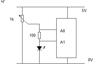
i finally started working on my school project. My first task is to measure IV curve of different LED diodes, but before this i need to make sure i am able to measure a single values of voltage and current. Is this diagram safe to plug in? Some people on arduino discord helped me to come up with this.
My second question is how i measure voltage and current (in code). Basically i know that voltage is difference of potentials, so it would make sense to get the A0-A1 and then convert this to volts? But how about the current?
oh, right.. so, i measure voltage like i stated and then simply do I=U/R like i would in a classic circuit? alright, that's simple, don't know why this idea hadn't popped up thanks alot
The way it's wired A1 is always reading zero (ground).
The 20K resistors are not needed. The analog inputs have nearly infinite resistance so (almost) no current flows through the 20K resistors and there is no voltage drop across them. (Resistors in series can useful as "current limiting resistors" in case you accidently connect more than 5V (or more than Vcc) to an input, you won't fry the Arduino.
The Arduino measures voltage relative to it's ground.
You just need 1 resistor and If you reverse the diode and resistor (with one end of the resistor grounded) you can measure the voltage across the resistor and subtract 5V to get the voltage across the LED. (Voltages sum in series.)
Or the way it's wired now, you're measuring the voltage across the LED so you can subtract to find the voltage across the resistor.
Then, since the current is the same through series components you can use Ohm's Law to calculate the current through the (known) resistor.
Finding the "curve" is a little tricky because you don't have a variable voltage. I suppose you could put a pot in series (between 5V and the LED) and use a 2nd analog connected to the junction of the pot & LED.. Then you can subtract the two analog readings to get voltage across the LED, and again calculate the current (using the voltage across the known-fixed resistor).
Everything seems to be relative to 5V, but is it actually 5V?
Well... Nothing analog is perfect and no analog measurement is perfect. Digital can be perfect... We can easily count exactly one dozen eggs, but we can never know if we have exactly 1 gallon of milk...
Vcc is the default reference and if it's not "exactly" 5V that introduces an error. It will never be exact, but we could measure it and as long as it's stable and as long as we can measure it fairly-accurately we can get fairly-accurate results. Or, we just assume it's 5V and that's probably good enough.
And of course, the resistor tolerance introduces an error in the current measurements.
So, no measurement is perfect and home made I-V curve tester probably won't be as good as a commercially built & calibrated instrument. BUT, it should STILL give some useful results!
That is a good start, John, but, you need a buffer between the voltage source and the load
or the 100 ohm resistor and LED will severely load down the 1K pot!
Thanks alot everyone for your help. i didn't have much time lately so i couldn't try this out, but today i finally did. It works! (i didn't use those 20k resistors, voltage between those pins is 2.6 V, is that right? ) You are right, if i am to vary voltage it would make sense to use potenciometer, however i can't. This project is supposed to be connected to a server later and has to work remotely, so i have to come up with something that alters the voltage without touching the hardware. Does anyone have an idea how could i do that? I've seen that johnny posted a solution without a pot, however i am not sure that i am able to do something like this, it looks complicated.
Edit: nvm i think i know - i can use pwm on my arduino as john does in his solution, thanks alot for your help again