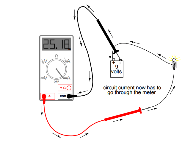
I am trying to measure the current used by an MCU device which I am using. I understand I can do this by putting the multimeter device in series like this.
When I connect the circuit like this (i.e. without the multimeter) the device powers on (see the LED). However, when I connect the circuit like this (i.e. with the multimeter in series) the device does not power on (although the multimeter registers a voltage).
Please could someone let me know what I am doing wrong?
i measured the resistors and the are exactly the right value and i dont know what else can be the problem.
Switch the meter to measure current ("A"). In the picture, you're clearly set for voltage. That's a high impedance mode so almost no current flows through the meter, and virtually all of the voltage is "dropped" across the meter.
In current mode, the meter is (almost) a short circuit so "be careful" in the current mode. In some cases you can fry your circuit if it's not connected in series with something to limit the current. And, blown current-fuses are common in meters so if you can't measure any current you've probably got a blown (internal) fuse.
Many meters have a separate connection for current measurement and that makes it less likely to short stuff out, but yours only has a separate connection for high-current measurements.
DVDdoug: Switch the meter to measure current ("A"). In the picture, you're clearly set for voltage. That's a high impedance mode so almost no current flows through the meter, and virtually all of the voltage is "dropped" across the meter.
In current mode, the meter is (almost) a short circuit so "be careful" in the current mode. In some cases you can fry your circuit if it's not connected in series with something to limit the current. And, blown current-fuses are common in meters so if you can't measure any current you've probably got a blown (internal) fuse.
Many meters have a separate connection for current measurement and that makes it less likely to short stuff out, but yours only has a separate connection for high-current measurements.
Thanks. I've setup as follows and switched to amps - still no amps showing and the device is not powering up (no LED on).
Measuring DC/AC Current
• Connect the black test lead to COM jack and the red to the
VΩmA jack for a maximum 200mA current.
• Set the rotary switch at the desired A /A~ range position.
• Connect test leads in series with the load under measurement.
• The polarity of the red lead connection will be indicated along
with the current value.
Note:
• When the value scale to be measured is unknown, set the
range selector at the highest position.
• When only the figure '1' or '-1' is displayed, it indicates an
over-range situation a higher range should be selected.
• " " means the socket mA's maximum current is 200mA and
10A's maximum current is 10A, over current will destroy the
fuse. Since 10A is not fused, the measuring time should be
less than 1 second to prevent precision from affecting by circuit
heating.
So if you anticipate over 200 mA use the 10A range and 10A connector. When unknown always start with the highest range, in this case 10A and remember the 10A range is not fused. The 200 mA range is. Keep in mind the current draw of an uC be it an Arduino board or any other will vary depending on what the uC is doing. Like any processor. If you see current fluctuations it may be perfectly normal, keep that in mind. Positive meter lead to positive of power source and negative meter lead to your load positive terminal. That gets you in series with the load. Even if you reverse the meter leads worst case is the meter will read a negative current.
sbaratheon:
Please could someone let me know what I am doing wrong?
Sure can. The first wrong thing is to wire up the circuit without determining in advance whether or not the connections you will make are appropriate. The second wrong thing is using the wrong settings for a measurement device.
When wiring up a circuit, make sure that the battery terminals are connected to power your devices with the correct 'polarity'.
And for your multimeter, electrical current measurements will not only require the multimeter to be switched to 'current measurement' mode, but also to know in advance that the multimeter will be able to handle the amount of current that will be flowing ------- so as to avoid a fuse blowing.
This multimeter allows has TWO configurations for the cables for measurements of current.
One configuration ------ with red coloured cable in the red coloured socket, and black coloured cable in the black coloured socket ------ has a approximately 200 mA current limit ------ and exceeding that limit (or there abouts) will blow the 200 mA fuse.
The other configuration, with red cable connected to the yellow socket, and the black coloured cable remaining in the black coloured socket -------- has a higher current limit ..... up to 10 A. And exceeding that 10 A (or there abouts) will blow the 10 A fuse.
One way to see if your 200 mA fuse has blown - is to disconnect the multimeter from everything, then turn off the multimeter, and open it up ------ to remove the 200 mA fuse. And then visually inspect the fuse - to see if it has blown. Otherwise, you can use the multimeter to measure the resistance of that fuse ----- to see if it has blown.
sbaratheon:
I did this just now and the battery just started to get very hot and there was a burning smell!
Perhaps you connected the leads across the supply instead of in series, a common beginners
mistake.
Current measurements are in series, voltage measurements are across.
When you've finished with your meter put the lead back in the voltage socket, switch to voltage
range - otherwise sure as eggs is eggs next time you use it you'll short something out through
forgetting the meter is configured for current....
Its also common to have burnt out the fuse in the mA range though getting this wrong - normally
only the 10A range is unfused - always start on that current range before selecting a more
sensitive range. And don't forget to check which socket the leads plugged into.


