Dear all,
I am trying to read the COM output from my EPEver Tracer 1210AN using a Mega+WiFi board via a Max485 module.
My primary orientation and references are the following...
-
Similar project based on NodeMCU, Max485 and Blync:
Cheap MPPT Controller Live Stats on Mobile - Hackster.io -
Pretty much the project of me except for the arduino board being different and a different charger model is being used, I copied the code from the screen, the code has strong similarities with previous orientational project reference code:
TUTORIAL: How To Use RS-485 TTL MODBUS - Arduino Controller Module (Part 2/2 - Wire Up) Solar - YouTube -
This is the best reference on the pins of the RJ45 and the EPEver device, the official manual does not have anything on the COM except to use their own pricy products:
python - Can't connect to EPsolar Tracer 3210an charge controller from Windows 10 via Serial / Modbus - Stack Overflow
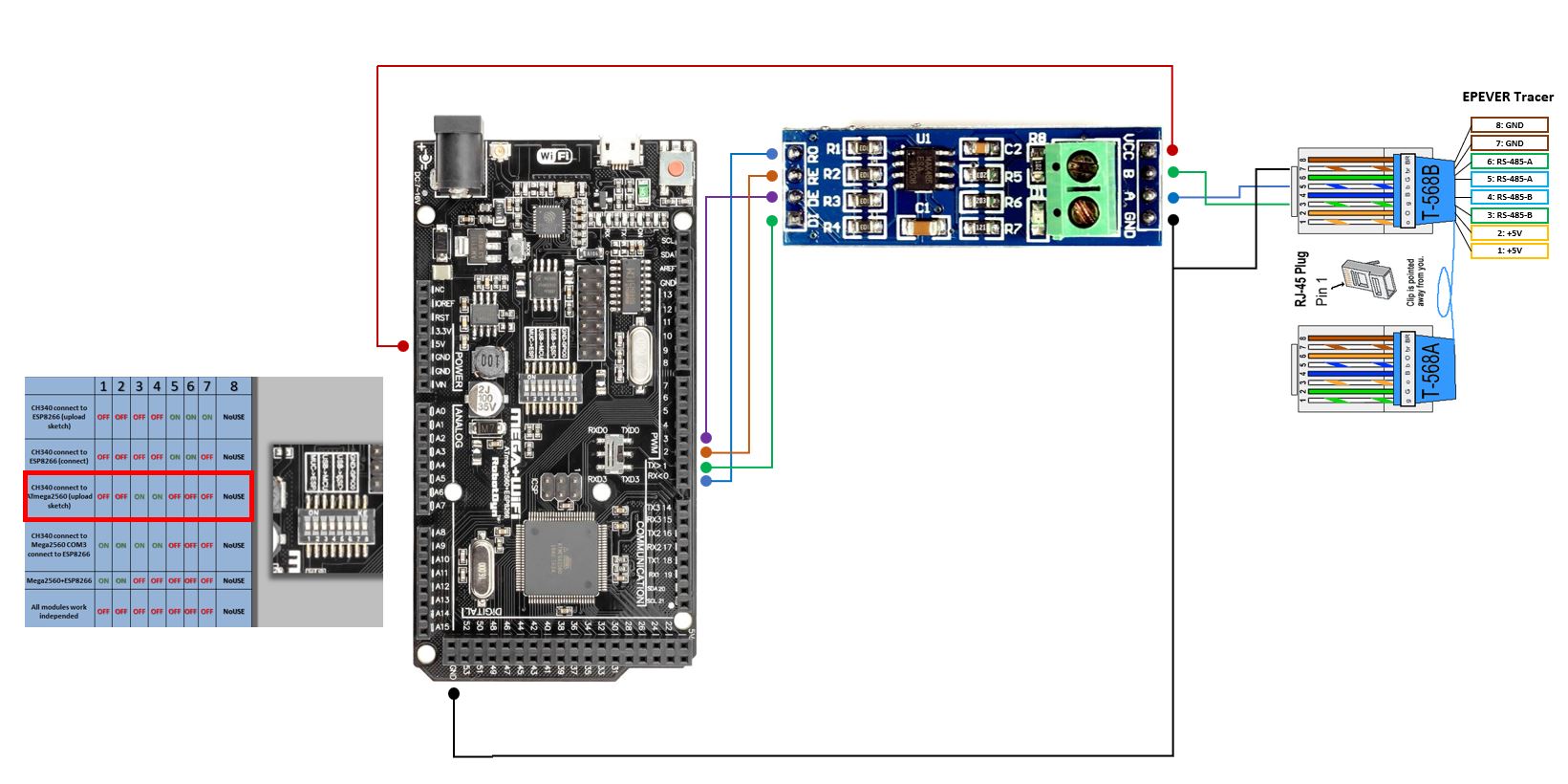
Wiring:
COM RJ45 Pin 3 (B) to Max485 B
COM RJ45 Pin 5 (A) to Max485 A
COM RJ45 Pin 7 (GND) to Mega+WiFi GND
Max485 GND to Mega+WiFi GND
Max485 VCC to Mega+WiFi 5V
Max485 DI to Mega+WiFi TX D1
Max485 DE to Mega+WiFi D3
Max485 RE to Mega+WiFi D2
Max485 RO to Mega+WiFi RX D0
Used code:
#include <ModbusMaster.h>

#define MAX485_DE     3
#define MAX485_RE_NEG 2

ModbusMaster node;

void preTransmission()
{
  digitalWrite(MAX485_RE_NEG, 1);
  digitalWrite(MAX485_DE, 1);
}

void postTransmission()
{
  digitalWrite(MAX485_RE_NEG, 0);
  digitalWrite(MAX485_DE, 0);
}

void setup()
{
  // put your setup code here, to run once:
  pinMode(MAX485_RE_NEG, OUTPUT);
  pinMode(MAX485_DE, OUTPUT);
  // Init in receive mode
  digitalWrite(MAX485_RE_NEG, 0);
  digitalWrite(MAX485_DE, 0);

  // Modbus communication runs at 115200 baud
  Serial.begin(9600);

  //Modbus slave ID 1
  node.begin(1, Serial);
  // Callbacks allow us to configure the RS485 transceiver correctly
  node.preTransmission(preTransmission);
  node.postTransmission(postTransmission);
}

void loop()
{
  // put your main code here, to run repeatedly:
  uint8_t resultMain;

  resultMain = node.readInputRegisters(0x3100, 6);
  if (resultMain == node.ku8MBSuccess)
  {
    Serial.println(" - - - - - - - - ");
    Serial.println("PV Voltage: ");
    Serial.println(node.getResponseBuffer(0x00) / 100.0f);
    Serial.println("PV Current: ");
    Serial.println(node.getResponseBuffer(0x01) / 100.0f);
    Serial.println("Battery Voltage: ");
    Serial.println(node.getResponseBuffer(0x04) / 100.0f);
    Serial.println("Battery Charge Current: ");
    Serial.println(node.getResponseBuffer(0x05) / 100.0f);
  }

  delay(1000);

}
I tried different BAUDs including 115200, all I get is garbage output on the serial. It seems that I am close to have it working but for some reason the reading is not good.
I have no previous experience with modbus, and a good portion of above code is just copied with good hope of working.
Appreciate any feedback, hints and suggestions that might get me some steps further or even to the finish line.
Many thanks!