Arduiono + MAX7221 trouble... leds not bright?

posting a new thread.. as I have things wired up..but am having issues with the brightness I am getting:

I soldered up one of the led 'matrix' strips....

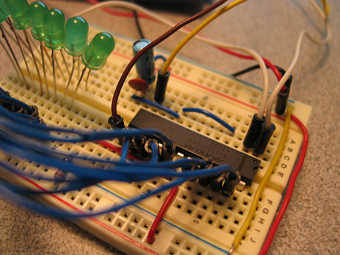
grabbed a MAX7221 chip, my Arduino and a breadboard.

prototyped up the circuit per my images and the data sheets/tuts..

I tried to be as proper as I know how..

pre-tin all my 'pads' of the 5050 led's.. (all 120 of them!!!!!) to make 2 x 60 led strips each.. (60 per MAX7221 chip).

solder my backing 'wire' that is also doubling as my GROUND bar/wire (just a thin brass wire to serve as something to mount my leds to and use for common ground).. when everything is all said and done.. I'll go back and cut the GND wire at every 8th led as needed.. but for now its keeping things together.. until the positive wires are complete...and the backing is applied

here is my first one.. a bit 'janky'.. but you'll neve see the strip itself.. it'll be inside the prop.. the second one came out MUCH better very uniform and tight spacing.. (I use a bit of a 'jig' to slide the leds into place and solder them.

fired it up, worked out a few bugs I had in the jumpers/code..uploaded it.. and gave a 'look-see'. =)

background of the physical set-up/wiring.

I took a long, thin brass rod/wire and soldered 120 x 5050 leds to it.. bridging 2 of the 3 GND's and soldering them to the brass wire.. I did this on all 120 x 5050 led's..

so basically are all sharing 1 huge common ground.. (for now).. I dd this to help keep things aligned and uniform during soldering. (also this led strip.. will eventually make a half circle.. (and the other strip making the other half of the circle).

I then cut up 120 x little 'wires' the length of 8 x 505 led's..ore-tinned each end.. and continued to solder each wire to connect the leds (#0 led to the next group of 8 leds #0 led..etc..etc then the same for the #1's in each group of 8 leds..etc.. like a matrix needs to be wired)..

I have NOT cut the GND bar at every 8th led (yet) until my final installment into the prop.... but wanted to give a quick test to see if wiring went ok..

I was thinking if I use DIG0 from the MAX7221 to the common GND wires being used.. and then use SEGDP connected to just the #0 led in the first group.. all #0 (SEGDP) positioned leds will light up in each 'segment'.... (because of the common GND for now)..

so I uploaded this simple test code:

//We always have to include the library
#include "LedControl.h"

/*
 Now we need a LedControl to work with.
 ***** These pin numbers will probably not work with your hardware *****
 pin 12 is connected to the DataIn/Din/DIN 
 pin 11 is connected to the CLK 
 pin 10 is connected to LOAD 
 ***** Please set the number of devices you have *****
 But the maximum default of 8 MAX72XX wil also work.
 */
LedControl lc=LedControl(9,8,7,1);

/* we always wait a bit between updates of the display */
unsigned long delaytime=50;

/* 
 This time we have more than one device. 
 But all of them have to be initialized 
 individually.
 */
void setup() {
  //we have already set the number of devices when we created the LedControl
  int devices=lc.getDeviceCount();

    /*The MAX72XX is in power-saving mode on startup*/
    lc.shutdown(0,false);
    /* Set the brightness to a medium values */
    lc.setIntensity(0,15);
    /* and clear the display */
    lc.clearDisplay(0);

}

void loop() { 
  lc.setLed(0,0,0,true);
}

to just turn on, initialize and clear the MAX chip..and then turn on the first led in segment 1 (which, again, in turn will turn on all #0 leds due to the common GND wire not being separated/cut yet)..

it 'worked'!.. but the leds were VERY, VERY dim.. (I am only using 2 of the 3 smd leds housed under the 5050 led housing/dome)

vLed(v)
Iseg(mA) 1.5 2.0 2.5 3.0 3.5
40 12.2 11.8 11.0 10.6 9.69
30 17.8 17.1 15.8 15.0 14.0
20 29.8 28.0 25.9 24.5 22.6
10 66.7 63.7 59.3 55.4 51.2

SO there was 8 leds on at the one time.. (8 x section/segments, 1st led in each on) 8 x 40mA total (2 leds on out of 3, 20mA each = 40mA total per 5050 led..treating it as 1 led unit that draws 40mA total).. taking 240mA total? well under the limit the max7221 can give..?? (similar to if I had turned on all 8's in 1 section/segment)

I then disconnected my led strip.. and took my desktop PSU.. turned it to v3.0+ and only 40mA current and connected the led strip to it.. same way I had done the MAX7221 (one clip to GND one to #0 led).. and it lit up VERY brightly.. like it I believe it should be.

I am thinking maybe I have the Iset/Rset resistor wrong? I believe I am using a 10kOhm resistor.. which is probably a bit UNDER what it recommended by a 'smidge'?

Anybody suggest some troubleshooting advice here?

I wouldnt think its not a circuit layout problem..being as it 'works'... but not as bright as it should (ie: like I can look at them directly..and see the two leds under the dome faintly lit...one when is lit normally you cant do that.. much less having two lit)..

I even tried editing brightness value just to test/see..

pics of the set-up breadboard.

could it be because I have NOT split/cut the common GND into its respective 8 led 'sections/clusters'? and the GND is common for all 60 leds right now?

I read 1 MAX7221 can be powered by the Arduino.. but more would need external power....

but if I wanted to supply/use external power.. I see where the change of the v5+ is...but where does the GND go form the battery pack? I see we need to use the Arduino GND for the circuit.. but where does the GND line go from the battery pack if we choose to use external power?

Im completely stumped on why I am not getting bright leds?

if there is anything else I can provide to you help you, help me.. just say so! =)

thanks

I don't about the brightness, but the grounds all have to be connected together.

HI-

Thanks for the reply!

So your saying that if I was to try using an external power source (which I will eventually use in the end project) I take the v5+ out the Arduino...use 5v from my benchtop PSU for now......and just add the GND to the current GND 'rail'?

because right now..they all use the same GND rail (tied together)...so just add the negative from psu/battery pack to the same rail...

thanks.

Im hoping this will help troubleshoot the source of the leds being so dim?

if anybody else has any ideas or sees an error in what Im doing, advice is appreciated!

:smiley:

Yes, all grounds must be connected together.

I don't know why you're not using the Arduino SPI pins to send commands to the SPI capable MAX7219.
I would put a 100nF from its power pin to nearest ground as well.

Remember also that the LEDs are multipexed at an 800Hz rate, so chip is not pulling the current you think it is.
I can only guess that your wiring setup with all the ground connections vs the chip driving 8 anodes and sinking 1 common cathode at a time is having an affect.

Each segment here is 3 LEDs in parallel being driven as 1 LED by a MAX7221, with current set at 6mA or so, and its nice & bright (alth hard to photograph well).

CrossRoads:
Yes, all grounds must be connected together.

I don't know why you're not using the Arduino SPI pins to send commands to the SPI capable MAX7219.
I would put a 100nF from its power pin to nearest ground as well.

Remember also that the LEDs are multipexed at an 800Hz rate, so chip is not pulling the current you think it is.
I can only guess that your wiring setup with all the ground connections vs the chip driving 8 anodes and sinking 1 common cathode at a time is having an affect.

Each segment here is 3 LEDs in parallel being driven as 1 LED by a MAX7221, with current set at 6mA or so, and its nice & bright (alth hard to photograph well).

Thanks..

Im not sure about SPI....its new to me. Im just following the tuts and the datasheets to the best of my ability.
Just using the approaches I have read for the software/libraries...etc

also in the end this will be used with that custom board, so there ill be DAC & uSD already in use.. (which I havent gotten to playing with yet either)

Im using the MAX7221

  • I have since snipped the ground.. and am dealing with only 1 group/segment now,..

  • still the same code as posted above.

  • all grounds tied together

at this point Im thinking it has to be the strip (physically?)

I mean Im by no means experienced in electronics.. but this seems like a fairly straight forward circuit diagram to follow..

Im gonna check on another set of 8 leds tomorrow and post back.

thanks

**also ( didnt even know you were a moderator CrossRoads?..new?)

can I get this moved to the LED & MULTIPLEXING forum... should probably have been posted there.. better traffic and its not really part of the end project yet..just getting familiar with the individual aspects of what I want to do, in the end.

Yes, have been a moderator for a while now.
AWOL usually moves the topics around. I can try it.

hi-

thanks or the topic move... (was hoping to get more advice in this section... guess not!) LOL

Well unless its a faulty chip (some how).. I am lost.. and sorta dead in the water I guess.

I have even taken the led matrix strip OUT of the equation and went to testing only 1 (5050 bridged) led instead... and still it does NOT get very bright..

maybe Im just expecting to much out of these things? but when powered by a PSU (directly) they are blindingly bright! when in use with the MAX7221 chip.. they stink! I changed out to a 4.7k resistor to try if things were a bit different...

=( =( =( :0 :0 :0

well I screwed something up.

in my attempts at trying to get the 'darn' leds to light up half-way decently... I ruined something, something.

Now nothing works.

Im not sure if its my Arduino at this point or what?

I cant getthe MAX7221 chip to light up 'anything'!!!!!.. it does nothing!!!! :0. I switched to a new chip as well to see if it made a difference..... still nothing.

Im nto sure if in 'code' somewhere.. or through the circuit physically or what. I was testing '1' single led to see if it would light any better last night.. then nothing.. no light..

I rebuilt whole circuit on a different breadboard and tested again.. still nothing. (2 steps back when all I wanted was the leds to shine correctly!... needless to say Im a bit upset, and disappointed in myself.....grrrr).. ok now that that is out.

Im hoping maybe someone can spot something I cant/done?

I took the Arduino and ran some blink sketches on default..and others pins I was using for this demo.. to see if maybe they were damaged or something?.. but they all worked/ran the sketch fine and blinked the leds...etc.. its like the Arduino will not communicate with any MAX7221 chip anymore?..or somehow the chips are initializing/working? (when previously they were? and even a new chip?)

I can meter whatever anyone suggests?

I know you guys like/need code & pics.. so here they are:

CODE:

//We always have to include the library
#include "LedControl.h"

/*
 Now we need a LedControl to work with.
 ***** These pin numbers will probably not work with your hardware *****
 pin 12 is connected to the DataIn/Din/DIN 
 pin 11 is connected to the CLK 
 pin 10 is connected to LOAD 
 ***** Please set the number of devices you have *****
 But the maximum default of 8 MAX72XX wil also work.
 */
LedControl lc=LedControl(12,11,10,1);

void setup() {
    /*The MAX72XX is in power-saving mode on startup*/
    lc.shutdown(0,false);
    /* Set the brightness to a medium values */
    lc.setIntensity(0,8);
    /* and clear the display */
    lc.clearDisplay(0);
}

void loop() { 
  lc.setLed(0,0,0,true);

}

PICS: (easier to follow now)

hopefully.. its something just super stupid I did? and nothing permanently ruined?

if the Arduino was ruined..it wouldnt play other sketches especially on the same pins..right?

but then how can other brand new MAX7221 chips not be working in this set-up either?

(wheres the punch myself in the face icon?) lol..

thanks

I'm not in a location where I can actually sit down and study your pictures and what not. Actually having to deal with a late bus on a school field trip right now. However, just out of curiosity, flip one of those LEDs around on the breadboard. Just humor me. Turn it around 180 degrees and plug it back in. If that's not the problem, then it's something else and like I said, at this point I can't do a whole lot. Later this evening after my meeting perhaps.

I tried that last night as well (thinking I might have had to rows/cols flip flopped)..

but no luck!.. I'll try again tonight when I get home to ensure.. but when i touched my leads from PSU to then (touched GND probe to connected/bridged GNDs on leds/board).. and ran my V++ probe over each leg.. and they all lit..

(was making sure I was trying to test with any dead leds)

Im hoping I just accidentally erased something in code? or fat fingered something (somewhere).. although the code is pretty short.. and I dont see any errors that jump out at me.

maybe a simple blunder on the physical circuit layout with e breadboards/caps or something?

and alternately, how can I ensure I didnt somehow ruin my Arduino? Like I mentioned, it runs different example sketches (blink for example).. I changed blink sketch to use different pins (pins 2-12).. just to check a few pins to ensure they still worked after being hooked up to max circuit/demo..

they all worked for a blink sketch.. so Im stumped as to how I cant communicate with the MAX any more?

Look at it tonight or when you get some free time (or are bored!) LOL..

Im disappointed in myself, that I have taken steps BACKWARDS.. instead of fixing the dim leds from my initial problem. :0

thanks for staying with the wondering (same) MAX topic with me guys!

appreciate the help.

In situations like this, I tend to rip everything out, start completely fresh with a clear board and all. Reconnect everything one by one. It's possible you have a wire in the wrong hole in the breadboard and you're just not seeing it. Happened to me. So I usually rip everything out, start fresh, and I do the same with the code. I open a new window and start completely new with the most basic of basics. I won't even go into programming what I want it to do, I just write the most bare bones sketch, just to turn the segments on and off, one by one, and go through the full thing, meaning I start at DIG0 and test each segment. Then switch to DIG1 and test each segment, etc., etc.

Once I figure out that it works, then I move forward.

yeah thats what I did.. (started over) I had my initial set-up above.. (big breadboard..long wires..etc)..

was having problems with getting only a 'dimly' lit led.. even though I beilieve iSet resistor was set properly...

after a few attempts of checking things with a meter.. and trying different leds.. it stopped working all-together.

couldnt figure it out..

I swapped to new breadboard, carefully re-wiring, and making it cleaner with short/tight jumpers where I can.. still getting same outcome.

I posted the new, cleaner set-up again to see if any problems..

the only code I was using was documented examples.. and what I believe was working before (albeit dim leds) LOL..

but again now Im getting nothing..

I usually only get a few hours (if that) on any given night after work/kids.. so I try to discuss, search and plan during the day..so time at home is spent on applying ideas/theories.

I was thinking this project was going to be fairly simple too!.. (outside of physically wiring up the matrix 'strips')

(boy was I mistaken! lol)..

(i'm gonna start bringing my Arduino and stuff to work so I test on my off time)

thanks!

pdate:

brought my set-up to work today.. re, re-did all the wires.. this time I replaced some of the 'male/male' jumper pins with some regular old solid core 'jumper wires' like you get from RadioShack..

and 'now'.. I am getting the matrix working again!.. WOOT!.. (I guess was a faulty wire.. I believe it may have been the CLK lead)..

anyways.. this was just on my junk set-up.. with 1 x 8 led segment/section.. tonight I will go back and see test on my 'true/real' led strip.. and see if this brings me back to my DIMLY lit led problem.. or if this cured that problem as well.

If I get DIM leds (again).. I have no idea what could be the problem at that point!

off topic question..

1.) what is the main difference between using code like I am.. (the led control library).. and the SPI interface as I have seen mentioned?
Is it speed? I believe the MAX7221 supports SPI and the MAX7219 does 'not'...

I have 7221's in this application.. but if I dont end up using SPI interface.. I can just swap out for the 7219's and save these..
but in the end my 'larger' project will be using SPI interface for both SPI and DAC (audio access & playing).. currently playing, breaking down one piece at a time of the larger project puzzle!

Thanks for the feedback and discussion KirAsh4 & CrossRoads!! couldnt have gotten this far without the guidance/thoughts.

Glad to see you made some progress. I didn't do much the last couple of nights, feeling a little under the weather.
MAX7219 & 7221 will both work with SPI. 7221 just needs a high-going edge to clock in the data after the SPI.transfer() commands, while I think the 7219 acts more like a latch, lets data flow thru and then holds the output when the SS pin is high.

If the LED library is not working as you wish, then I would back up and use discrete commands so you know what is going on.
I can post what I have done to drive my large box for setup and for writing the 8 individual registers after that. The only difference would be that you are running in No Decode mode, whereas I was send ing data to output the characters. But you could start with that even to show it works, and add the command for the change of mode.
I know its posted in the forum already, but that can be tough to locate. I'll post again after fencing classes tonight.
You are sure the LEDs are wired up as common cathode, yes?

Yeah.. Im glad it was a faulty wire... (but the 'true' test will be when I get home and try to drive that led strip of 60 x 500 leds!.. which has two GNDs bridged and 2 positive legs bridged.. treating it as 1 led.. needing/pulling 40mA each then)..

which says to use a 10.6k ohm resistor.. (but those leds were KAKA as far as brightness)

What is the difference between using SPI? and the way I have copied/used from the demo/examples posted around here? (not difference in the code per se`.. as I saw an older post of you yours where you write bits to registers..etc.. very detailed control it looked like..

where as the LedControl class seems to have some easy to use pre-made functions/methods for us.

(seems like it should suit my needs.. however I am a bit far off form implementing/writing the final code.. as this will be used in conjunction with that custom board and audio clips..etc)

So is SPI 'better' (or desired) due to performance? or are there are advantages? (learning curve for noobs?)

ooops.. sorry failed to answer..

yes, they are all common cathode/GND.. as you can see from the above posted pics of the led strip, all leds are soldered to one (shared) brass line/rod this server as the common cathode/GND bar as well as structural support from the led 'strip' 9and the half circle shape it will eventually be bent to fit)

the current set-up on the mini breadboard is only a group of 8 leds.. (for mobile testing purposes).. but those too are set-up as common cathode/gnd.. (and all seem to work fine).. they are generic, diffused green leds form radio shack.. so I can not comment on the brightness currently.. when I check with the real 5050 led strip, I'll be able to see if they are really getting what i feel is enough juice to power them correctly/brightly..

I have a side question on using a PSU in general..
I take my PSU..
set voltage to 3.0v+
set current/amperage to 40mA+ or so..

I test on an led.. if I see the current 'move' and show positive number in there? (like its drawing more current?) what does this mean?
is it taking more than the 40mA I set it to or something?

thanks

Tell me again how you're wiring 8 LEDs? You're using two channels, so each one would pull 40mA. Do you have all 8 driving from one DIG and one SEG pin? Or are they wired as one DIG pin, and 8 SEG pins?

first thing I did was (in the first post images) solder 2 x GND legs on the 505 together (bridged two gnd's)
second I did was bridge the matching 2 positive legs together.. (essentially making 1 led 'unit' from the two smds under the same dome)

so 'each' 5050 led only has 1 GND lead (2 bridged pads) coming from it.. and each 5050, has 1 positive lead (2 bridged pads) coming from it

all 8 leds have a common GND/tied together..

each of the 8 leds positive leads go to 1 segment on the MAX chip.

so 8 x leds total

all 8 have the same/common GND

'each' of the 8 led positive leads go its respective segment pinout ....to DP, SEGA, B, C, D..etc..

currently.. I dont think its a hardware problem.. (as I have it running/working all day now.. a simple up/down animation on the 8 leds)..but this was just using the test bed (8 green leds from above pics).. NOT the true 5050 led strip I will use in the end.. and what I had originally posted on about being lit very DIMLY..

so I am 'back' to square one (so to speak)..

I am on my way home in a few hours to test the ORIGINAL led strip.. this I could NEVER get to be 'bright' by any standards...

as far as using two channel (bridged....acting as 1 led/unit).. that is correct.. and it should pull 40mA.. correct.

I am using a 10kOhm resistor as my Iset/Rset resistor.. tryign to be in the 40mA range according to the resistor chart they provide.. (but never actually made the leds BRIGHT.. they were very (very) dimly lit...

maybe this 'bad' wire was part of the problem? only way to check is when I get home I guess..

thanks

Yeah, the 10K would be correct for that range ... approximately. They should light up bright based on your description of each individual LED wired to a SEG pin (with all of them having a common ground DIG pin).

(messed up what I meant to say)

You should have all A, Bs, Cs, Ds, Es, Fs, Gs, DPs, connected in parallel going to the same MAX7221 pin.

Each set of ABCDEFG-DG should have a common cathode that goes to 1 of the 8 DIG pins.

Is that what you have? There is no Ground involved with the LEDs. Just the parallel segments, and the shared Cathode that goes to a Digit pin.

yes that is correct/how it is wired up..

sorry I used GND.. but yes the (2 bridged) cathodes on each led (per grouping of 8) are all tied together, going to DIG0 (which in my mind I of as GND0)

(wired just like in the pics above).. if it were wrong.. they wouldnt be lighting up at all right now...right? not doing the animations/scanning...etc.... right?

You should have all A, Bs, Cs, Ds, Es, Fs, Gs, DPs, connected in parallel going to the same MAX7221 pin.

correct

Each set of ABCDEFG-DG should have a common cathode that goes to 1 of the 8 DIG pins.

correct,..
I only have DIG0 wired up..but of course DP, A, B, C, D, E, F, G all have wires (going to individual leds)

the only ting I can think of is:
before today.. I had a 'suspect' jumper that led to my loosing the circuit completely.. and re-building it on a smaller, cleaner scale..
I just got it back 'working' today.. so I have yet to try the original 5050 led strip to see if it 'shines bright' now or not..

anyone care to enlighten me on the PSU behavior I see sometimes? where you set the voltage and the current.. hook it up to something.. and you see the current readings jump/move a bit? Is something wrong? pulling more mA?

thanks!!

this question from below:

I have a side question on using a PSU in general..
I take my PSU..
set voltage to 3.0v+
set current/amperage to 40mA+ or so..

I test on an led.. if I see the current 'move' and show positive number in there? (like its drawing more current?) what does this mean?
is it taking more than the 40mA I set it to or something?