Hello all, I'm trying to use my arduino uno to act as a an EEPROM device to send its contents over a 1-wire to a master. I've already tested the master with a DS2431 EEPROM chip filled with data and it's able to read the data just fine, now I'm trying to emulate this chip with an arduino.
After doing some research I found a handy library which seemed to be exactly what I needed called OneWireHub.
Which contains a sample program for emulating a DS2431, exactly what I was looking for.
So after downloading the libraries, wiring the data line to an interrupt pin (2), I ran the sample program with everything looking just dandy. However I'm not picking up anything on the data line aside from "FF." So what gives?
I'm seeing plenty of activity on the 1-wire bus, I know the master is working properly because it was used previously, so that leaves me at a loss as to what I could be missing. The only alteration I made to the example program was changing the pin from and "8" to a "2" (as 8 isn't an interrupt pin on the uno) but aside from that everything is the same. Am I misunderstanding how to actually use the OneWireHub?
You do know that the example emulates the 144 byte EEPROM in RAM and not in the EEPROM of the UNO, do you? So if you save something to the emulated chip and disconnect power, everything is gone.
However I'm not picking up anything on the data line aside from "FF."
So, how do you do that? Did you attach a logic analyzer?
I'm seeing plenty of activity on the 1-wire bus,
That contradicts the above sentence. What exactly do you measure and how?
The only alteration I made to the example program was changing the pin from and "8" to a "2" (as 8 isn't an interrupt pin on the uno) but aside from that everything is the same.
The pin doesn't have to be an interrupt pin as the code doesn't seem to be interrupt driven but simply reading the input pin quite often.
The pin doesn't have to be an interrupt pin as the code doesn't seem to be interrupt driven but simply reading the input pin quite often.
+1
After much testing, I believe the main compatibility problem is the response time to the master. When the master pulls the line low to read a bit, the Arduino is barely fast enough to respond with a zero bit. This is crucial when the master is discovering addresses. Some masters treat a slow zero response AS IF it were a one response. Things go downhill from there.
I've been mulling over the design of a circuit to latch zero bits instantly. A transistor or two on the 1-wire pin, plus another digital pin and some discretes might do it. Anybody else go down this path?
pylon:
You do know that the example emulates the 144 byte EEPROM in RAM and not in the EEPROM of the UNO, do you? So if you save something to the emulated chip and disconnect power, everything is gone.
Yes the board always has power so I'm not concerned with that.
pylon:
So, how do you do that? Did you attach a logic analyzer?
pylon:
That contradicts the above sentence. What exactly do you measure and how?
Right sorry, poor choice of words on my part. I do have a logic analyzer and while I'm seeing similar pulses the emulated chip isn't matching up to the real one.
(I've attached what I'm seeing to this post)
pylon:
The pin doesn't have to be an interrupt pin as the code doesn't seem to be interrupt driven but simply reading the input pin quite often.
Also correct, I misunderstood that part so I've been sticking with pin 8 as in the example.
-dev:
After much testing, I believe the main compatibility problem is the response time to the master. When the master pulls the line low to read a bit, the Arduino is barely fast enough to respond with a zero bit.
That's also something I'm concerned about but from what I understand it's been tested and should work...
That's also something I'm concerned about but from what I understand it's been tested and should work...
As far as I understood it they tested with two masters. Is your's one of the two types that they tested with?
The pictures you posted both show only 1s, the emulated signal looks exactly the same as the EEPROM signal. Are you sure your master is working correctly?
No its a different master than those two but it's working correctly as a master. I've been able to have it correctly read 3 different (real) DS2431 chips that I wrote unique values to just fine.
Any values that I have on the chip look the same when being read so I'm not sure what other kind of pictures you'd like to see.
I would like to see a picture where some '0's are sent, that means that the data line has to be pulled low for at least 60µs, all shorter pulses are '1's.
As both the "original" signal as well as the emulated look exactly the same I can just guess that you measured the wrong period of the signal.
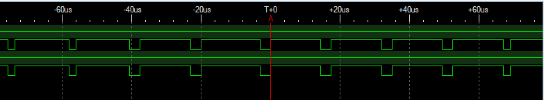
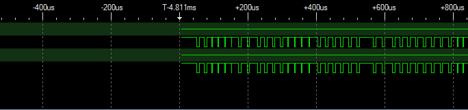
Hmm maybe these will be more useful then. It's a capture of each signal as they begin before they all turn to ones. Albeit it seems like the real chip is only ones....
When you are comparing traces, it would be nice if you use the same time scales.
Why two identical traces? This is a 1-wire protocol, after all.
And keep the image width below 600 or so. As you can see, the wide images get scaled by the forum to the point of unreadability. It's "inconvenient" to download a file, then view it...
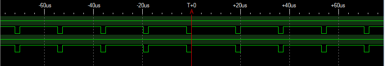
Right sorry, here's some better captures. I'm still trying to get the most useful looking parts in a single image so let me know if you still want more.
What's the signal of the real chip before the part that is visible now? Because that part in the emulated picture conform to the 1-wire protocol as the standard defines it. The rest seems to be a much faster version. If the real chip has the first part identically too, that part seems to switch to the faster protocol (perhaps for backward compatibility.
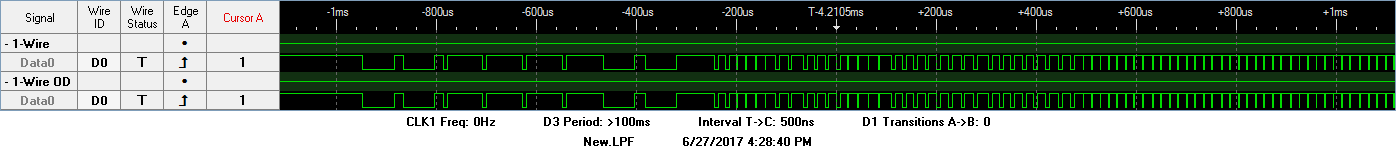
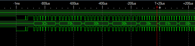
Yes I forgot to mention in each picture the bottom signal is overdrive. Here's a clearer example of what's going on with the physical chip (Which is full of 0's).
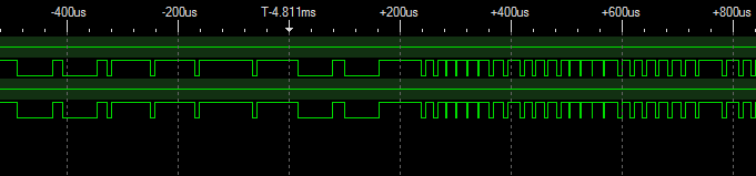
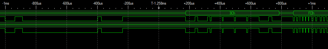
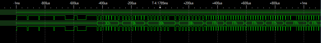
Here's also a better look of what's going on in the emulated signal. Seems like its not working in overdrive even though the emulator ought to support it? (Sorry its rather too large to embed)
Oddly enough I had changed that value but it seemed like I was getting the same results shown in my previous posts. I went ahead and deleted the library, re-downloaded and changed the value again. Now the line appears to be switching back and forth from overdrive (seemingly more often than the chip). When its in OD I'm seeing 3Ch (Overdrive command) followed by F0h (Search ROM command) much like the actual chip. However after two 00h's the line goes back to FFh...
The DS2431 emulation that is delivered with the OneWireHub library doesn't support all features of the original chip. The Overdrive-Skip ROM command is not supported. If your master needs that special features you have to write your own version with all commands supported.
It also seems that your master doesn't enter the overdrive mode the usual way (reset shorter than 80µs) but that's only a guess from the logic analyzer pictures you posted.
I would record a complete access loop of that master with the logic analyzer, write down all features of the DS2431 that are used by that mystery master and then write an emulation of the chip that supports at least these features.
But isn't Overdrive-Skip ROM supported in the OneWireHub file through the hub.poll function?
You're right, I didn't look into the code deeply enough.
What I'm still don't understand: In the emulated picture we see almost one byte in standard speed (I guess it's 0x3C too), but in the chip version we see only overdrive speed. Is that because you didn't scanned at the same part of the communication or does the real chip really not have any standard speed communication? Have recorded once the original reset command?