Correct! My mistake. The maximum current of the read switch as well as the limit of the 5 volt "supply" is the limit.
It is a reed switch! ![]()
Are you using a phone with auto-incorrect like Grumpy Mike? ![]()
Likely capable of "some current", yes.
Surely funny but I don't catch it....
I particularly would not use two wires per reed, I would use one as common GND for all and one return for reed, only 11 wires. And as already indicated @Railroader configure the pins in PULLUP with their internal resistors.
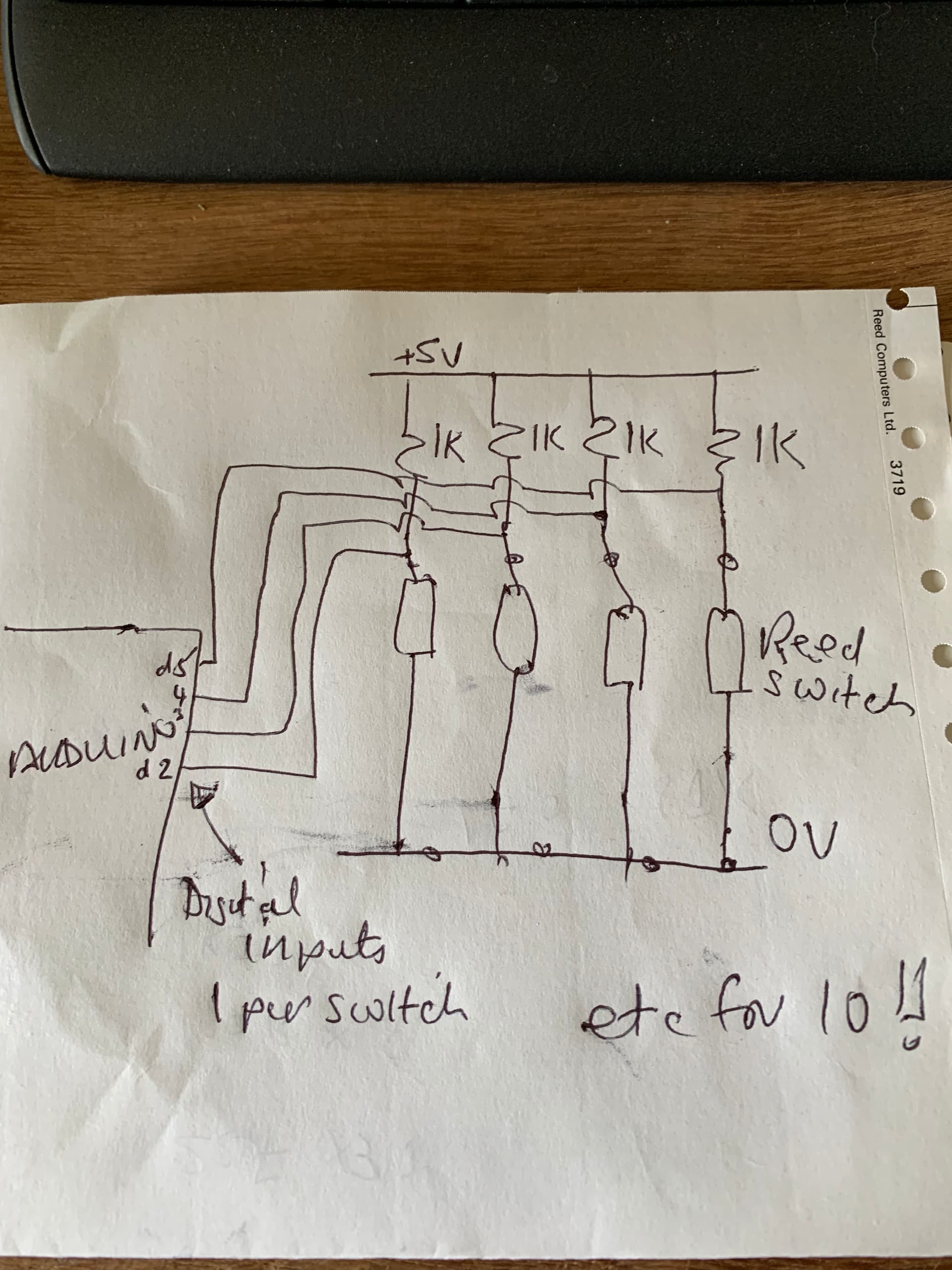
The electrical scheme is simple:

And some basic code for testing:
void setup() {
  Serial.begin (9600);
  for (int n = 2; n < 12; n++) {
    pinMode (n, INPUT_PULLUP);
  }
}

void loop() {
  for (int n = 2; n < 12; n++) {
    if (digitalRead (n) == HIGH) {
      Serial.print (" Window Nº");
      Serial.print (n);
      Serial.println (" it's open");
      delay (250);
    }
  }
}
That's no good. The pullups must be near the receiving end to work the best. Read switches usually have not "pullups". Pulled up to what?
That is a mistake. Use a least twisted pair cables between the switches and the controller. That will be much more resistant to electrical noise. A spider network of grounds and lonely signal cables is not advisable.
Yes, that code is good for testing the setup.
You can use a 5 x 2 matrix, or for the same pins, a 4 x 3 and have 2 open for control switches or sensors.
Reed switches are cheap but so are Hall Switches which are transistor-fast and sensitive so that weaker magnets can work.
Don't confuse a digital Hall Switch with an analog Hall Sensor that costs 4x or more.
Also, Hall devices measure field along 1 direction. There are many types of Hall devices., be sure before you spend!
You may be right. He has the wires and the reed, he already tried it in PULLDOWN, let him try it this way and see what happens, it doesn't cost anything.
Inductance and local lightning strikes make spikes!
It's even worse if the wire has a bend that encloses much area.
But bypass caps can eat those.
Would a current loop system work better? Those are pretty standard.
If the task is monitoring doors glitches ought to be easy to handle. Doors seldomly travels at lightning speed....
Commercial alarm systems "alarm" when the reed switch is open. Is this what you are designing?
Now I am a bit more confused ![]()
@Paul_KD7HB correct.
As @gonpezzi correctly said, I've all the wires and reed sensors already in place, with no intention/chance to change anything in the existing setup.
The infrastructure is designed to be compliant with a VdS certified alarm system (a standard i.e. here in Switzerland). The sensors even have 4 wires each (2 wires for open/close, 2 wires for sabotage detection). Instead of relying on a commercial system, I just want to read the reed sensors myself, but only the open/close states, the sabotage contacts do not matter for now.
@Paul_B thanks for the hint with placing the resistor on the 5V lane. But, I don't get why the resistors should not be placed close to the sensors. My priority is to protect the sensors against unwanted side effects of other wires/cables in the near - not the Arduino that can be replaced easily.
@GoForSmoke what kind of bypass caps would you suggest?
Now I've got a few different solutions from you ;-). I will try my best to check what will work best for me. Thanks so far for the fast replies and help from you.
And against exactly what "unwanted side effects" are you "protecting" the reed switches? ![]()
@Paul_B , one of the vendors of such reed sensors wrote an article about exactly this question
It states: if possible, you should place a resistor near to the sensor to protect the sensors from inrush currents that might occur.
That's how I just implemented the design, based on the suggestions so far - with a quick live test.
Except one thing: @Paul_B you've suggested to put the resistor on the 5V lane instead of on the ground lane. There are some threads, where others say it should go on the ground, to have a solid "low state". That is the only thing that I would like to sort, before doing further live tests.
After that has been sorted, I'll move the resistor as close to the reed sensor as possible, as "standexelectronics.com" has stated.

@Paul_B , unfortunately I cannot answer directly, due to the limitations of new joiners. Therefore here the message:
You don't have to be sorry ![]() . That is why I am asking. Despite the fact, that vendors tell and promise, that their switches will have a lifespan of billions of operations and are made for these - there are unfortunately a lot of switches that have been damaged - even though powered with 5V and without any kind of violations in the infrastructure - only because of the mentioned and described side-effects. I just want to make sure that I am not one of those unhappy guys with damaged reed switches.
. That is why I am asking. Despite the fact, that vendors tell and promise, that their switches will have a lifespan of billions of operations and are made for these - there are unfortunately a lot of switches that have been damaged - even though powered with 5V and without any kind of violations in the infrastructure - only because of the mentioned and described side-effects. I just want to make sure that I am not one of those unhappy guys with damaged reed switches.
So I wonder, did you read it?
Switching no load or loads where the voltage is less that 5 Volts @ 10 mA or less, the contacts undergo little or no wear. Here life times in excess of billions of operations are expected and realized.
I'm sorry, but it seems you have nowhere near the knowledge to discriminate what you are reading and are becoming confused. ![]()
I’m not sure if the multiple sensors bit was understood , but with my organic graphs tablet ….This is how I would basically do it
There can be issues with long cables though and I would probably go with opto isolators and/or bit of filtering -but worry about that if it happens .
If it’s an alarm system you might want a “tamper loop “ too.
What to use depends on those wires but consider that
digutal chips can be like diesel motors, lots of rattle. The AVR needs 2 for the noise it makes. Bypass caps are like springs.
I'm more of a bit-head, you have EE's here to tell you better and more.
That's about induction powering a surge in unshielded wire.