First of all I want to specify that I'm a total newbie to arduino and in electronics in general.
I'm approaching to Arduino and I bought "The Arduino Starter Kit" from the Arduino Store (the board is Arduino UNO).
I just completed "Project 02" but there is a thing about the electronic schema that I don't understand (maybe a little early to have dubts? ).
The project is very simple (attached an image of the electrical schema): basically there are 3 LEDs connected to 3 pins (output mode) of Arduino and a switch connected to another pin (input mode). The result is the switch controls the powering on/off of LEDs.
As you can see in the schema, there is a 10K-ohm resistor placed between the switch and the groud: why this?
About this, the instructions says "You'll also need to add a 10k-ohm resistor from ground to the switch pin that connects to the Arduino. That pull-down resistor connects the pin to the ground when the switch is open, so it reads LOW when there is no voltage coming in through the switch".
Sorry, but I still don't understand. I mean, when the switch is up, the circuit is not closed, so the electricity doesn't pass through: so which is the function of the 20k-ohm function?
So, I said: "let's try to replace the resistor with a wire and see what happens", but when I press the switch it seems that Arduino powers off and reboot.. something about crashes and reboots to avoid damage...
Can you please help me to understand this?
I repeat, I'm totally dummie about electronics, please be patient..
The switch connects the pin to +5V so it needs a pull-down resistor. An unconnected
pin (think about the switch being open and no resistor present) will float (its voltage
will vary at random due to capacitive pickup from the surroundings - a pin in input
mode carries no current (to a good approximation) so picks up any nearby influence.
The standard way to connect a push button is between the pin and ground, allowing
the built-in pull-up resistors to be used (pinMode (pin, INPUT_PULLUP))
lucapolitti:
As you can see in the schema, there is a 10K-ohm resistor placed between the switch and the groud: why this?
So that the input to the pin is connected to something - it's in a known state. If you don't connect it to anything it can give random values (it picks up radio waves, etc.)
lucapolitti:
So, I said: "let's try to replace the resistor with a wire and see what happens", but when I press the switch it seems that Arduino powers off and reboot.. something about crashes and reboots to avoid damage...
Of course it will, you just connected 5V to GND with your switch.
Hi. I was reading your post and I have a question about the placement of a resistor in the RedBoard guide. I'm also new to electronics so pardon me.
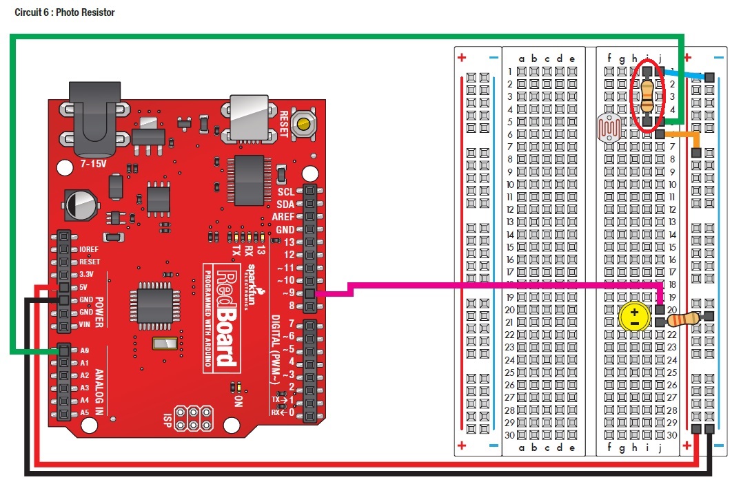
The following circuit uses a photo resistor to control the brightness of an LED. I was wondering why the resistor(circled in red) is placed after the photo resistor, instead of before. If the resistance of the photo resistor were to drop to a very low value (close to 0), would there be a short-circuit because the 5V pin would be directly connected to A0? Or is there like a minimum resistance for a photo resistor?
Hope to be enlightened by your knowledge. Thank you.
I was wondering why the resistor(circled in red) is placed after the photo resistor, instead of before. If the resistance of the photo resistor were to drop to a very low value (close to 0), would there be a short-circuit because the 5V pin would be directly connected to A0? Or is there like a minimum resistance for a photo resistor?
no, ther would not be a short-circuit here. The wiring is 5v-LDR-resistor-GND , and A0 connected to the LDR<->resistor junction .
if you put the resistor between 5V and LDR, it will work, but you'll get t a reverse information :
wired as it is, if the light is brighter, the LDR resistor is lower, and the value on A0 increases .
If you put the resistor between 5V and the LDR, when the light is brighter, the LDR resistor is lower, and the value on A0 decreases.