I am designing a small board whose goal is to automate some tasks by interacting with several sensors (nothing new under the sun I guess). The project will use a 12v external source and a pair of LF50 and LF33 will provide 5v and 3.3v voltages to other ICs on the board. I am also wiring an ACS712 IC to monitor system power consumption. So far so good (at least on paper!).
Now, what is troubling me. I need to control a few 12v outputs through releais and most importantly I need to forbid those releais to provide more than 1amp each to the controlled external devices. Please consider that those devices may be LED lamps, water pumps, etc...
Relais control is fine through 2SC3649T-TD-E transistors (although there might be better choices) but I am slightly unsure about the current limiter options. What would you suggest?
I was thinking about adding current limiter ICs or swapping entirely the transistors in favor of the ICs (if I am not mistaken the MP5016 is supposed to have an Enable pin that may entirely shut it).
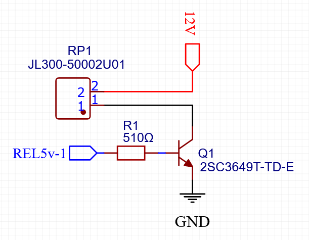
Guys, thanks a lot for the feedbacks. To make it clear, this is the part of the schematics that I'm referring to.
REL5v-1 is my GPO on/off switch controlling the Q1 transistor.
RP1 is the connector I want to use to power my external devices.
As said, I need both to control on/off state of this circuit and max current (1amp) when state is on. Consider that my RP1 connected actuators are not known in advance and may go down to request only a fraction of max current...
Thank you dearly to all of you.
@Railroader please see my explanation here if that helps.
@stevemj quite of a noob here, I'm reading about the SMARTFETS right now. Thanks a lot.
@jim-p also reading about those current monitors. Thank you.
@paulpaulson I know a bit of the infamous xy-problems myself but it honestly doesn't look like that to me. If you do, please explain why.
@david_2018 Thanks, I know I could use fuses but that is not what I am looking for. As the external controlled device is not known in advance I would like to use something softer than fuses that would only prevent the port from working until a less hungry device gets wired to it.
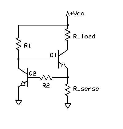
R1 is your input, Rload is your relay. Rsense set the current limit (R = 0.6%V / I_limit ). I do not think R2 is really needed. I've designed in millions of these. Simple, low cost and effective.
It sure is but..... Suppose the worst case of a load being 0 Ohm, short circuit. Transistor Q1 will then discipate Vcc * 1 Watt. That calls for a good heatsink.
As already told, when the current limiting goes active the load doesn't get Vcc at all. One method practiced was to give the controller a signal and the controller switched the relay off.
Giving the large picture hade given helpers better information and more motivation to attack the question.
Know that way to often ignorant members ask for detail solutions and later come back telling: "It doesn't work.".... Their basic idea was not useful but helpers spent time figuring things out.
Not saying just Your ignorant!
Of course it does. The point is that I have 4 of these transistors lines acting as relay and each of the present transistors supports 1.5amps. As the psu allows more than 60w in total I don’t want to have these little guys end up in smoke.
Hi, I am checking the polyfuse right now and it seems an interesting solution. If I am not mistaken (english is not my native language after all), when amps limit is reached, it basically shuts any current until back in range. I am not entirely sure if this is the behavior I was looking for but I'll try to get my head around it. Also, as much as probably all possible solutions I must consider the voltage drop...
When you say "are they heatsinked" you mean what? If you are talking about the current transistors I am using, these are SMD without an actual heatsink.
SMD have a heatsink, it's supposed to be on the PCB board. The data sheet will have information about thermal conductivity and dissipation vs. the board layout. So I mean, what does that look like?
when amps limit is reached, it basically shuts any current until back in range. I am not entirely sure if this is the behavior I was looking for
Well, it certainly sounded like what you were looking for...
It doesn't just reset when the current is back in range. There is a thermal timeout.
Regarding the heatsink: yep, as you correctly say I only have the one on the board I thought it was clear... but I still don't see how this would help solving my current limiter question. Also, as much as the Polyfuse sounds nice indeed, I was more looking for limiting power to a specific threshold and much for shutting down the line when threshold is reached.
That could wreak havoc with some devices. Especially if you have no idea what they are a priori. Essentially, you could inflict a "brownout" on it, low voltage and significant current... Am I right, you don't want a "foldback" feature, where an overload triggers a low current state until the load is removed?
You could run the output from a voltage regulator instead of a transistor. It has limiting circuitry.
Otherwise you are looking at a very customized and component heavy solution.
Simple, basic output current limit circuits are very ancient and mundane, been around since about 1950 in audio amplifiers... look there.
No offense taken mate. I apologize if the question may have sounded a bit simple in the way it was formulated: I am more of a software person (electronics noob in the best of cases) and english is also not my native language!