I didn't know you could use the analog inputs as outputs, how is that done?
Just set the pinMode() to OUTPUT and they behave as digital pins.
I didn't know you could use the analog inputs as outputs, how is that done?
Just set the pinMode() to OUTPUT and they behave as digital pins.
Knightriderguy:
I didn't know you could use the analog inputs as outputs, how is that done?
almost every channel has a second or third capability.
some of the Digital Outs have the ability to be PWM
some are set to be uses as serial communications lines, 0 and 1, for RX and TX , 11/12/13 for PCI
on the analog side, pins 4 and 5 are used for I2C communications.
as was noted, if you define the pin in the void setup() as an output, it will work exactly like a digital out put in your sketch.
here is a link to a listing of most of the pin uses.
http://pighixxx.com/unov3pdf.pdf
UKHeliBob:
Just set the pinMode() to OUTPUT and they behave as digital pins.
Hey there UKHeliBob been a while, thanks for chiming in on that ![]()
Cheers ![]()
Here are a couple on links to the relay board close up views of how the Optocouplers are installed on the relay board if it will help clarify what is what with this particular 16 channel relay board.
Yes, exactly the one (I don't think there are any other ones).
This board is designed to also supply the Arduino (shared VCC/5volt and ground). No options.
This might be ok, but as said, I don't know what happens if you connect a computer to it that is connected to the same car battery.
Option 1 then. Plug and pray.
Leo..
Wawa:
Yes, exactly the one (I don't think there are any other ones).This board is designed to also supply the Arduino (shared VCC/5volt and ground). No options.
This might be ok, but as said, I don't know what happens if you connect a computer to it that is connected to the same car battery.Option 1 then. Plug and pray.
Leo..
Thanks Leo,
Sorry for the very late reply. Only just now getting to the stage where we REALLY need a good relay board solution for our Dash software project. I recently picked up the Arduino Mega because it has lots more ports for our project. Ideally I would have loved to have used a relay board that had a lot of relays but if the optocoupler-isolation is not there then I guess two or three of the 8 channel relay modules with the optocoupler-isolation would be better.?
I wonder if it might be possible to use a Optocoupler-Isolation board or module if there is such a thing?
What about using diodes to prevent feedback through the Arduino?
Demo Video of part of the project function
Yes, it really looks like the inSainSmart relay board ... previously there was no easy way to isolate the ground. Now, after looking at the schematic and pcb files, they're using the on-board regulator's 5V to power the opto-isolators IRLED. The ground issue looks resolved, but now there's no easy way to isolate the board's 5V from Arduino's 5V.
At least it can be done, and its easier than other revisions ... just need to cut the trace marked here
Now full opto isolation can be achieved (check that you have the exact same board first).
16ch schematic.pdf (54.6 KB)
16 RELAY.pdf (230 KB)
dlloyd:
Yes, it really looks like the inSainSmart relay board ... previously there was no easy way to isolate the ground. Now, after looking at the schematic and pcb files, they're using the on-board regulator's 5V to power the opto-isolators IRLED. The ground issue looks resolved, but now there's no easy way to isolate the board's 5V from Arduino's 5V.At least it can be done, and its easier than other revisions ... just need to cut the trace marked here
Now full opto isolation can be achieved (check that you have the exact same board first).
Thanks If the modification to the board is simple I don't mind doing it, just one of my concerns is that if we sell packages to people I don't want to be constantly modding relay boards if there is a better option available ![]() ?
?
This is the one I have, I took some closeup pictures:
 16 Channel Relay Board Back Of Optocouplers by Michael Knight, on Flickr
 16 Channel Relay Board Top Optocouplers by Michael Knight, on Flickr
Very nice images!
I haven't used these boards (but might purchase one and give it a try) so I'm not 100% sure this would work. However, this looks like the only spot required to cut the trace in order to isolate the board's 5V regulator output from the 5V pins.
After cutting the trace, the board's 5V regulator should only provide power to the transistor side of the opto isolators and other coil-side circuitry. On the opto LED driver side, it would require a 5V connection to Arduino. After trace-cut, should measure with an ohmmeter and get something much greater than 0 ohm from the 5V pin(s) to pin4 of any opto isolator (transistor collector).
Here's the spot on the top side of the board (hope it works!):
dlloyd:
Very nice images!I haven't used these boards (but might purchase one and give it a try) so I'm not 100% sure this would work. However, this looks like the only spot required to cut the trace in order to isolate the board's 5V regulator output from the 5V pins.
After cutting the trace, the board's 5V regulator should only provide power to the transistor side of the opto isolators and other coil-side circuitry. On the opto LED driver side, it would require a 5V connection to Arduino. After trace-cut, should measure with an ohmmeter and get something much greater than 0 ohm from the 5V pin(s) to pin4 of any opto isolator (transistor collector).
Here's the spot on the top side of the board (hope it works!):
Thanks I cut the trace like this See:
 20160320_151907 by Michael Knight, on Flickr
On my multimeter I get some odd numbers twitching when I hold the probes on the 12V power port and pin 4 of the Optocoupler.
I do get a continuity reading between the 12V Ground and the Arduino input grounds is that normal?
 20160320_151806 by Michael Knight, on Flickr
On my multimeter I get some odd numbers twitching when I hold the probes on the 12V power port and pin 4 of the Optocoupler.
What about the 5V input pins (all jumpers removed) and pin 4 of the Optocoupler?
I do get a continuity reading between the 12V Ground and the Arduino input grounds is that normal?
Its not desired because we need isolation there too. Are all jumpers removed?
No problem ... the GND connection is not required to the Arduino.
Here's the isolated connection scheme for the 8 Relay Module, should somewhat similar here.
dlloyd:
What about the 5V input pins (all jumpers removed) and pin 4 of the Optocoupler?
Its not desired because we need isolation there too. Are all jumpers removed?
No problem ... the GND connection is not required to the Arduino.
Here's the isolated connection scheme for the 8 Relay Module, should somewhat similar here.
Thanks I get a 0 reading if I hold a probe here and on the Arduino inputs for 5V
On the pin just above it I get a reading of 1 on the meter set on Ohms
 20160320_151907 copy by Michael Knight, on Flickr
Make sure its not bridged here (all gaps should be clear).
dlloyd:
Checking schematic / PCB files ........
I also get a reading on around 5 if I hold probes to pin 3 and the Arduino Ground Low Level input pin.?
What is the resistance from pins 1 and 2 of the opto isolator to each of the two 5V input pins (where the jumper goes)?
EDIT:
Further investigation of the PCB file shows at least 8 more (very difficult) areas to cut the 5V trace ... this makes it impractical if not impossible to manually revise this board to isolate the 5V rail.
I guess the board could still be used in non-isolated mode after repairing the cut trace.
Will they (SainSmart and others) ever get it right for using opto-isolation?? What a waste of costly parts, all they needed to use is the transistor array alone for a non-isolated board!
dlloyd:
What is the resistance from pins 1 and 2 of the opto isolator to each of the two 5V input pins (where the jumper goes)?EDIT:
Further investigation of the PCB file shows at least 8 more (very difficult) areas to cut the 5V trace ... this makes it impractical if not impossible to manually revise this board to isolate the 5V rail.
I guess the board could still be used in non-isolated mode after repairing the cut trace.
Will they (SainSmart and others) ever get it right for using opto-isolation?? What a waste of costly parts, all they needed to use is the transistor array alone for a non-isolated board!
Thanks, I guess I'll have to find another solution. I was kinda hoping the mod would be easy just in case I had to do lots more of them.
But is there a better board you could suggest that has actual optocoupler isolation?
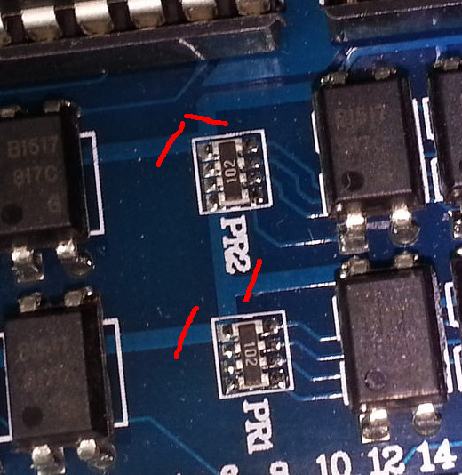
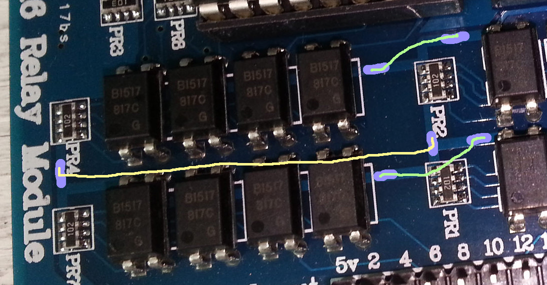
I told you many posts ago that I can talk you through it.
You only have to cut ONE track to opto-isolate the first 8 relays.
Four more cuts and three wires for the next lot of 8.
First picture shows the trace to cut for the first 8 relays.
Cut for the second 8 exactly where I showed, because you have to scrape away some paint next.
Solder three wires to the bare copper as shown.
Connect 5V (next to pin 1 and 2) to Arduino's 5volt pin, and the 16 inputs to the Arduino outputs.
Do NOT connect ground to the Arduino.
Leo..
I haven't heard of any issues with the 8 Relay Modules (with opto isolators). Don't know of any 16 Relay Modules that have properly configured isolation (yet). I'll be staying away from this one. ![]()
Wawa:
I told you many posts ago that I can talk you through it.
You only have to cut ONE track to opto-isolate the first 8 relays.
And, from memory, another four for the next lot of 8.Picture shows the trace to cut for the first 8 relays
Leo..
Thanks I cut that track.... what's next ? ![]()
Wawa:
Nope.
This relay board is hardwired to Arduino's 5volt rail.
Depending on which Arduno, it could backfeed your computer's USB port.
Leo..
I was originally using the Uno but now I have the Mega.