I tried connecting it directly to GND, but the background squares didn't even appear, it just turns a light blue (backlight) and nothing else. I think the problem is in the contrast, but connecting it to GND would solve it, and it didn't.

I developed it in stages. I first made sure the nrf24 module worked and then added the LCD.
I believe the problem is in the contrast, because you can't even see the "squares" in the background, but I'm not sure.![]()
But ok, I'll try to disconnect everything and focus on the LCD.
Can I suggest you write some code JUST for the display.
In fact use a library example.
Tom... ![]()
![]()
![]()
![]()

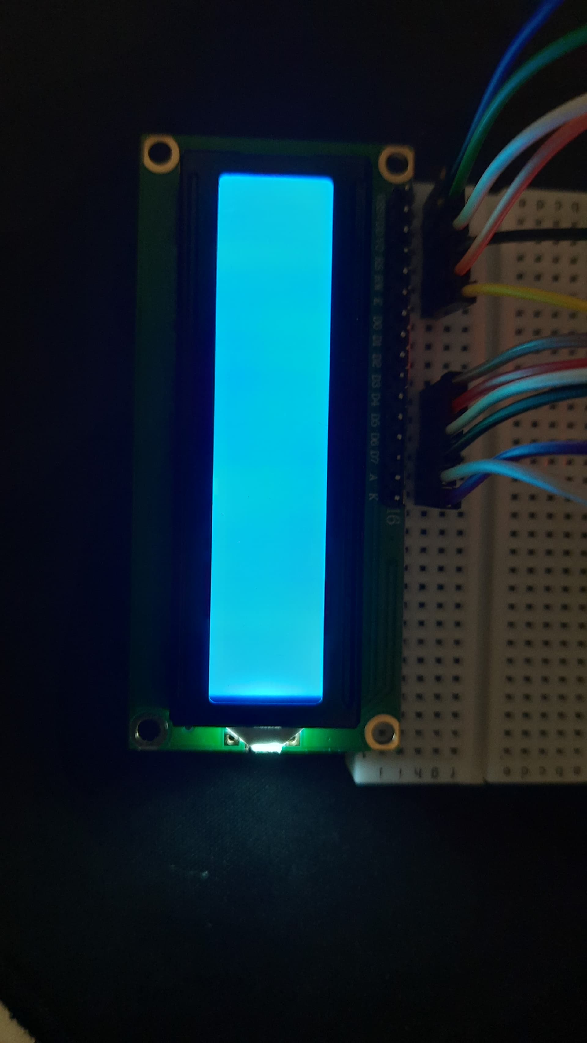

I removed everything and redid just the LCD part. I followed the tutorial in the link below, but the result remains the same, just an empty screen (as shown in one of the images)...Any suggestions?
Place a 10k potentiometer from VO to Arduino GND, adjust as needed.
Looks like you did not install the LCD header in a normal way.
Let’s see the display removed from the breadboard, i.e. solder side / bottom.


I think the OP is spending some time soldering the male header to the LCD PCB. ![]()
1 Like
You're right... ![]()
I'm trying to solder the pins to the lcd without completely destroying the connections. ![]()
I believe the lack of soldering is the problem.
![]()
Serious, where did it say:
do not solder the header to the LCD PCB ?
FYI

1 Like
The pins I used to connect the LCD to the breadboard are thinner than the holes on the LCD so there is a gap which could be causing the connection to fail. It may be that after soldering they will be well connected. ![]()
I was just experimenting with the lcd, didn't want anything permanent. That's why I haven't soldered the pins until now.
Header pins male/female must be properly installed and soldered.
You can not rely on friction fit connections to work in electronics.
33 posts to get to this point ![]()
1 Like
Sorry....![]()
I'm new with electronics. But it's pointed out, I'll try not to make the same mistake.
I hope that after the fix everything will be working.![]()
FYI


1 Like
Thanks! I will put this information to good use... ![]()
Have fun !
If there is doubt, continue to ask for advice on how to do stuff.
1 Like
Update:
The problem was the lack of solder. As soon as I soldered the lcd it started to work correctly. I just need to find a resistance to put in the contrast and backlight.
Thanks to everyone who helped me! ![]()
![]()
I had the same problem and anywhere in the whole net it is not said that V0 must be grounded. simulators work without it.
Than you so much!
Minor correction. Vo can be grounded or connected to ground through a resistor to control the contrast. Many people use a potentiometer.