srnet:
RESET, to the target processor, needs to be controled by the Arduino doing the programming.
The Arduino as ISP program normally uses pin 10 on the programmer Arduino connected to RESET on the target.
Do your schematic show this ?
Damn!!!
You find my obvious mistake, and I pass it all the time. Thank you. You have a beer if you ever come in this from God's forgotten country.
However, after I cut the wrong net port reset trace and bypass GPIO 10 with a wire to a DIP switch I get some unusual problem. With no MCU in sockets and DIP switches OFF, Atmega_Board_Detector.ino on serial terminal gives me some strange output and stops.
Atmega chip detector.
Written by Nick Gammon.
Version 1.20
Compiled on Apr 17 2020 at 18:05:15 with ⸮
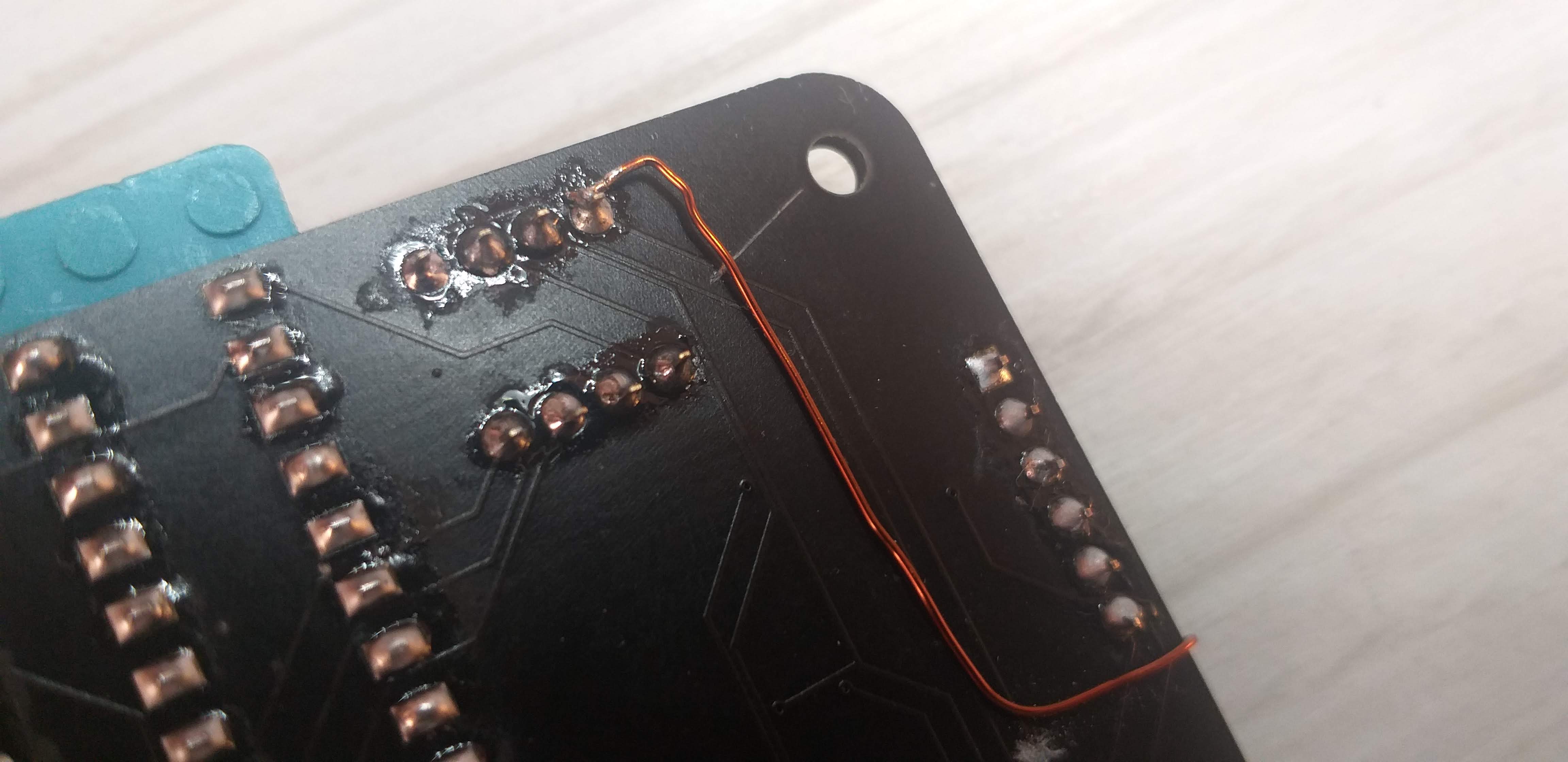
The same sketch when I unsolder wire (no matter from where), goes on to the point that it can not see any SPI connection to the other MCU. Which is as it was and it is ok. I cut the trace on two places as you can see on the pics. When the wire is soldered to the MCU, and the other part is not, it goes to the part that it can not see any MCU. When I solder the other part of the wire I get this on the serial monitor. Weird.
That pin of the DIP switch is not connected to anything, and when off, it is really non-connected.
Ok, it works!
I made a bunch of mistakes, but eventually, I made it work as it should. Thanks to @srnet above all, but the rest of you, too. Mostly of pointing to some other possibilities.
Issue nr1.
I noticed that I had 5V on the reset port net, no matter what I do. Actually, HIGH. On PCB design there was a trace from the PTH of the reset port net to the reset pin of U3. I didn't notice it because of the DIP switch. When I take a closer look at the spare PCB, I find it out. I removed the DIP switch to cut the trace because it was the only place to cut it and not cut the trace to the reset switch on the left. That way I removed that 5V from the upper PTH. But remains on the bottom.
Issue nr2.
The R4 resistor which I put there along with the reset switch for the socket MCUs causes the 5V on the bottom PTH. I unsoldered it, too.
With those two fixes, I easily burned the bootloader on my DIP Atmega328p.
I will make a revision of this board. On this one, I let there an FTDI programming header to upload a simple blink sketch. But it just doesn't need to be there. I will remove it. Both with the pin 13 LED.
If any suggestions, I am all ears.
Again, Thank you.
Hi,
TIP;
Having a PCB made in BLACK makes it hard to trace tracks.
Next time use GREEN, it is amazing how easy it is to follow tracks.
BLACK may look sexy, but its not practical.
Before you populate your new PCB, apply power and check the various pins and component pads for supply and gnd, in your case RESET pins in particular.
Tom... 
Yeah, black PCB is damn looking good, but not for prototyping.
I did check various things but missed the SS pin (10). I messed up in the schematics.