Hi everyone.
I have a question regarding the circuit of my current project. Im fairly new to building my own setup, so I apologize if this is a stupid question.
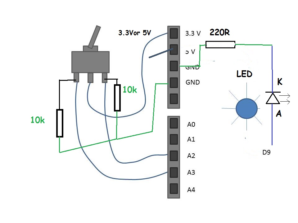
I would like to set the color of a led according to a mechanical switch. I have a Uno board, a NeoPixel LED and a MS-500C switch. I understand that the switch only has 2 'ON' positions (ON/OFF/ON), but my idea was to set in a way like this:
The two positions (1 and 3) are connected to analog inputs 2 and 3. If I get a signal on 2 the LED should glow, lets say red, if I get a signal on 3 the LED should glow yellow. If no signal is available the LED should glow blue for example.
Since I want to use the 5V output as a powersupply for the LED I need to use the 3.3V output as a switch signal. The LED part is no problem. But I have some questions about the switch. I attached a drawing of my current circuit. Would that work? Do I not need a ground for the 3V signal aswell or is it connected internally to a ground on the board. If so, how would I need to set it up?
Thanks everyone in advance and have a nice day.
Sen
You can use the 5V on the switch, but in either case you will need to add some pull down resistors so when ever A2 or A3 are not connected to your voltage, they are pulled to gnd.
Also your LED will need a resistor in series and wired as in the diagram so your logic will work.
The resistor is to limit the current flowing out of the Arduino and through the LED.
D9 will go high or 5V when you code the output to go HIGH.
If you do what Tom suggests you can use two digital inputs, and this really is "digital logic".
But... It's easier if you reverse the logic and use the [u]internal pull-up resistors[/u] and connect the common switch terminal to ground. (That way you don't have to add the external resistors.)
With two inputs there are 4 possible "binary" values:
00 (not physically possible with the double-pole switch)
01 (one input grounded)
10 (the other input grounded)
11 (switch in center with both inputs pulled-up)
...It's possible to use one or more voltage dividers (made with resistors) to give different-voltages with different switch positions, and then you read the voltage with an analog input. But, I kind-of hate to see people using analog for digital logic.