Yes, you've got it now
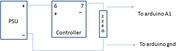
here,s a slightly improved image of the circuit
You do appreciate that the controller has to have the mains supply powered up before the 4-20 circuit operates.
I suggest you leave the arduino disconnected until you have proven you get the correct voltage developed across the resistor. (I note you called it a capacitor.
Man, I was thinking about the cap label all day.. I knew it was resistor.. LOL.
Thanks for the diagram. Much nicer.
One question. I see you have the arrows from the resistor to the Arduino coming off both sides of the resistor. Does it not matter which side of the resistor they are connected to?
is that the "same" as your image?
If both A1 and ground terminals of the arduino are connected to the same point on the resistor how is there going to be a suitable signal generated. - There won't be !
Another term often used for voltage is "Potential Difference" or PD for short. This term might give you an appreciation that you need a "difference" between two points to provide a measurable signal.
To get a signal into the arduino there must be a PD, This is created by passing a current through the resistor. The current in this case is your 4-20ma,
So, when the current, created by your controller (if it still works) flows through the resistor, a PD is developed in direct proportion to the current. Ohms law states that V (or PD) = I x R, where I is your variable current and R is the 220 ohm resistor.
You pick up this signal for feeding to the arduino as per MY diagram.
Note the polarity !!! The positive side (connected to A1) is the end of the resistor connected to terminal 7. The negative side (connected to GND)is the end of the resistor connected to the negative side of your power supply.
click goes the lightbulb.
Ok actually your diagram is like my original I was not "seeing" it correctly.
I get it!
Now to wire it up and see if she still works. If not; time for some warrenty action on my $300 controller
I could never get it to do anything. I called HM Meters today and the tech guy said it DOES NOT need external power...
He did say to run a 250ohm resistor between terminals 6 and 7. I cant really see how to put a resistor in between those and still connect to the arduino but I'll play with it this evening.
ill post back with results.
If the manufacturer states that the 4-20 circuit doesn't need external power then why does instruction No2 of the set-up procedure state that the 4-20 receiving instrument must supply the power ? Clearly there is a contradiction.
ONLY IF what he says is correct the resistor should indeed be connected across 6 and 7. As per their drawing 6 is +ve and goes to the arduino input, 7 is -ve and goes to arduino ground.
However, on the basis that there is contradiction between their tech help and their published instructions I would avoid connecting your arduino until such time as you have confirmed that you do indeed get 1to 5 volts across the 250 ohm resistor (or 0.88 to 4.4 if you use a 220 ohm)
I called HM Meters today and the tech guy said it DOES NOT need external power.
A current loop doesn't need external power if it is being connected to another (active) current loop. Did you explain what you were trying to do and did he understand, I doubt it. Power has to come from somewhere to drive the thing.
yea he didnt seem like he quite got it. But better than the first person I spoke to who said "yea it should be able to run on 4-20Ma"...
I now am getting sensor readings.
They change when I stick the probe in solution. yay!
however they arent in a 1-5 range like I expected.
heres my sketch
 */

// These constants won't change.  They're used to give names
// to the pins used:
const float analogInPin = A1;  // Analog input pin that the potentiometer is attached to

float sensorValue = 0;        // value read from the pot

void setup() {
  // initialize serial communications at 9600 bps:
  Serial.begin(9600);
}

void loop() {
  // read the analog in value:
  sensorValue = analogRead(analogInPin);
    // print the results to the serial monitor:
  Serial.print("\t sensor = " );
  Serial.print(sensorValue);


  // wait 1000 milliseconds before the next loop
  // for the analog-to-digital converter to settle
  // after the last reading:
  delay(1000);
}
With the controller displaying 0PPM (should be outputting 4mA)
I get a value of 8.00 - 11.00 on my serial output.
When I stick it in water of 400PPM the serial output jumps to 18.00 - 21.00
at 0ppm or 400ppm the arduino serial output varys a few points every loop.
but hey Im getting there.
And it seems the controller might not be torched
ints werent giving me a decimal place.
i assumed, probably incorrectly, that sicne it would be a range of 4-20 thats only 16 data points.
There would have to be decimals to get any kind of accurate readings.
So what circuit are you using - the one using external power or the vendor's last one using internal power. What voltages are you getting across the resistor. If these voltages are incorrect then your controller, whilst maybe not totally goosed may well be malfunctioning.
Im doing this now
Ok now im embarrassed to admit my volt meter isnt doing what it should. I think I broke off the power on the battery. its ancient. Once I resolder that Ill check the voltage.
never easy is it?
i assumed, probably incorrectly, that sicne it would be a range of 4-20 thats only 16 data points.
That is the range of the current loop interface it is not the range of readings you will get from the arduino. The arduino converts the input voltage its analogue pins into a number where 5v gives you 1023 and 0v gives you zero. It is unlikely that you will get any meaningful number without doing a bit of maths with the reading you get.
ahh. which is why the part of the sketch I cut out was there...
outputValue = map(sensorValue, 0, 1023, 0, 255);
so i need to convert 0-1023 into something useable.
so i need to convert 0-1023 into something useable.
Yes, all that mapping did was to in effect divide the reading by 4, you need to see what the numbers mean in your setup. At 5v each step of the A/D value is about 4.88 mV. (that is:- 5/1024)
Hi Mike
In Jockanese it is also a "load" but technically it isn't really a load, rather its a passive current to voltage transducer. But what the *ell we're having hard enough job trying to guide the originator on how to get his controller info into the micro.
jack