I was wondering if anyone can give some quick advise and sample code solutions? Don't lauph to hard for me saying that. I am very new to this and am running a simple sketch. I'm just reading an analog input (A5) from a spectrophotometer's output.
I have researched this topic in the Forum and some of the applications I read are far more complex than this setup. The values are pretty much spot on comparing them to a oscope but only display 2 integers (Ex. .080) All I want is to read 3 data values (Ex. .0823). Included is the sample code. Is there an easy way to do this without bit shifting, adding bytes....an so forth.
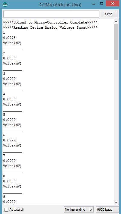
I spoke to soon. I understand the calculations above and thanks. The problem is I noticed the value (maybe in a pattern changes 2-3 times) sometimes displaying the correct reading. Checked with DMM and it appears to be a steady voltage when adjusting the system pot and taking a new reading? Look at the serial monitor pic I enclosed to see it better. I went though all the lines adjusting and nothing seemed to correct it but removing ,4 for decimal places. I'll have to look at the architecture better but you would think this wouldn't be very difficult and designed for these types of applications? Just a simple data recorder. Again, pretty green and haven't touched one of these sense college in a galaxy far far away.
11B73:
The problem is I noticed the value (maybe in a pattern changes 2-3 times) sometimes displaying the correct reading. Checked with DMM and it appears to be a steady voltage when adjusting the system pot and taking a new reading? Look at the serial monitor pic I enclosed to see it better. I went though all the lines adjusting and nothing seemed to correct it but removing ,4 for decimal places.
Perhaps the spectrophotometer output is not as stable as you think it is. The DMM may be too slow to register the changes, and the scope may not have the precision to show you the fluctuations unless the vertical gain is greatly magnified.
Or, you may have interference and/or a ground loop in the connection between the Arduino and the spectrophotometer.
The OP may use 1023 but it really should be 1024 And yes, you can only measure up to 1023 * (5/1024) = 4,995V, not 5V.
OP, you print mV but you just print the value in V. The change in value for a steady voltage is just because of the ADC error in de Arduino. The LSB is just flipping.
But, like I said many times around here, don't use floats. They are slow, inaccurate and not necessary.
I changed the code to not use floats. Also, 4 digits is "to much" for the 10-bit ADC in the Arduino. The reading isn't that accurate, every bit is almost 5mV. So I limited to 3 digits (but you can change it to 4 if you really really want).
/*
  Read Analog Voltage

  Reads an analog input voltage on pin A5 & common ground, converts it to voltage,
  and prints the result to the Serial Monitor.
  Attach the center pin of a potentiometer to pin A0, and the outside pins to +5V and ground.
  Includes a Loop Command for future use
  // Indicates Notes & Compiler Does Not Include
  ;  Semi Colon After Each Command

  Chad J. Stoltzmann 04-08-2015
*/

	// The setup routine Runs once when you press Reset:

	int Counter =0; //Simple Counter Loop (See Below to Close Loop)


void setup() {  //Needed in all Code!

	// Initialize serial communication at 9600 bits per second

	Serial.begin(9600); //BAUD Rate
	Serial.println("*****Upload to Micro-Controller Complete*****"); //Text
	Serial.println("*****Reading Device Analog Voltage Input*****"); //Text
}

  // The loop routine runs over and over again forever:

void loop() {  //Needed in all Code
	int sensorValue = analogRead(A5);  // Read Input V on Analog Pin (A5) and Ground on UNO R.3

	// Convert the Analog Reading (which goes from 0.00 - 1023) to a voltage (0.01 - 1V):

	//Do multiplication first to keep accurate. Long because 1023 * 5000 is to big for an int.
	unsigned long voltageInMv = sensorValue * 5000UL;
	//check for rounding errors, if remainder is larger then halve the resolution, add 1 mV
	if(voltageInMv % 1024 >= 512){
		voltageInMv = voltageInMv / 1024 + 1;
	}
	else{
		voltageInMv = voltageInMv / 1024 + 1;
	}


	Serial.println(Counter = Counter + 1);  //Simple Counter Loop Adjust (1) with Integers
	Serial.print(voltageInMv / 1000); 		//Print the whole volts
	Serial.print(".");						//Print decimal point on same line
	Serial.println(voltageInMv % 1000); 	//Print decimal places (up to mV) and end line
	Serial.println("Volts(mV)");    		//Text
	Serial.println("_________");    		//Text

	delay(1500);                    		//Delay(ms)
}
I'm still learning this forum and was looking to find how you reply to each post individually but with no luck. I was wondering about the 1023 myself? This goes back to Digital 101 and should be 1024 and was confusing to me. 1, 8, 16, 32, 64, 128, 256 ,512, 1024.........
I was wondering about the ground as well and constant signal values outputted by the spectrophotometer. This is reading off of a high end photocell and converting the photons into electrons producing the voltage (mV) output.
Is it the board ground connection? I had it on both the power side ground input and the opposite sides near the AREF pin? Both are giving me the same readings.
I agree that a scope of DMM might not pick up the slight variations from the photocell but based on both units again the signal appears stable?
Let me get to the septillion code (thank you!) and report back my findings.