Hmmm... I don't have any MOSFETs available, suppose I could buy one.
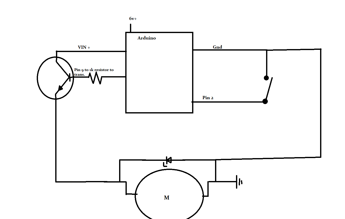
But back to Paul, I see what you mean now about having the gnd side as the switch (transistor in this case) I tried taking my existing circuit and swapping everything around backwards (in order to get the transistor on the gnd side) I swapped the diode around so that the stripe still was on the + side of the motor, kept the 1k resistor on the center pin of the transistor, to the pin 9 of arduino, etc. but now I get no movement of the motor. The transistor begins to heat up but no movement. I've tried switching to a different transistor, no luck. With the transistor on the + side of the equation it did work, albeit not 'properly' Next suggestion?
Could it be that the signal to the transistor is not adequate to run on the gnd side of the equation? Hmmm... new problem... Now if I remove from the USB and run on strictly the 6v power supply, it just keeps running continuous, I'm at 8m and counting.
daveyg1987:
Next suggestion?
Schematic please. Stop trying to use English to describe the circuit, it's too crude and ambiguous. Please start using the proper symbols, not ambiguous rectangles. Hand drawn with pencil & paper is fine.
Can I also suggest not connecting anything up until we've checked your updated schematic?
Let me know if this is any better. If there is a suggested program for creating more legible schematics please let me know. I'm a CAD/CAM machinist by trade and can draw a blueprint for a part with my eyes closed, but trying to use paint program for a schematic doesn't work that great.
Paul, I see what you mean now about having the gnd side as the switch (transistor in this case)
Did you see?
This is how it was connected when I tried to put the transistor in the gnd line path, and at the time it did nothing but cause the transistor to get hot. If this is how you would suggest I connect it I will try it that way once again and report my results. I have other transistors at my disposal as well if they would be more useful, BC557, and BC547, if either of those would be better suited to this application. I just started with the 2N2222 as that is what someone used in a video on youtube to control power to a similar motor to mine.
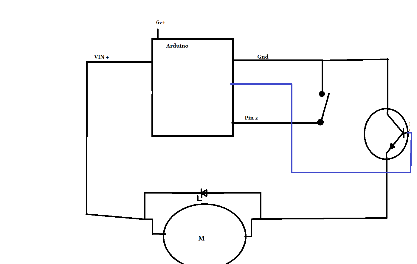
You have the collector and emitter pins the wrong way around, and the resistor for the base is missing.

That looks ok now. Wire it up like that. If the transistor still gets hot, replace it with another 2n2222. Don't use bc557, that is pnp not npn. Don't use bc547, it has a much lower current capability, only 100mA, which is much lower than the 600mA of the 2n2222.
Ok so set up like that, and with the following program, it works, and works fairly well, however there is one problem remaining, it does not shut off. Currently have the time set to run 2.5 minutes, and it occasionally turns off after 2.5 minutes, but more than half of the time it runs for 2-3x that long. Thoughts?
//Global Variables
const byte BUTTON=2; // our button pin
const byte motorPin=9; //pwm output to 2222 transistor

unsigned long buttonPushedMillis; // when button was released
unsigned long ledTurnedOnAt; // when motor was turned on
unsigned long turnOnDelay = 500; // wait to turn on motor
unsigned long turnOffDelay = 150000; // turn off motor after this time
bool ledReady = false; // flag for when button is let go
bool ledState = false; // for motor is on or not.

void setup() {
 pinMode(BUTTON, INPUT_PULLUP);
 pinMode(motorPin, OUTPUT);
 digitalWrite(motorPin, LOW);
}

void loop() {
 // get the time at the start of this loop()
 unsigned long currentMillis = millis();

 // check the button
 if (digitalRead(BUTTON) == LOW) {
  // update the time when button was pushed
  buttonPushedMillis = currentMillis;
  ledReady = true;
 }

 // make sure this code isn't checked until after button has been let go
 if (ledReady) {
   //this is typical millis code here:
   if ((unsigned long)(currentMillis - buttonPushedMillis) >= turnOnDelay) {
     // okay, enough time has passed since the button was let go.
     analogWrite(motorPin, 150);
     // setup our next "state"
     ledState = true;
     // save when the LED turned on
     ledTurnedOnAt = currentMillis;
     // wait for next button press
     ledReady = false;
   }
 }

 // see if we are watching for the time to turn off LED
 if (ledState) {
   // okay, led on, check for now long
   if ((unsigned long)(currentMillis - ledTurnedOnAt) >= turnOffDelay) {
     ledState = false;
     digitalWrite(motorPin, LOW);
   }
 }
}
Put some Serial.println("") in to help debug the code. Put one in setup(), and some in loop(), e.g. when the motor is switched on or off, and at other points of interest. Don't forget Serial.begin()!
daveyg1987:
// make sure this code isn't checked until after button has been let go
// okay, enough time has passed since the button was let go.
These comments are confusing. Your code never actually checks if the button was let go...
PaulRB:
These comments are confusing. Your code never actually checks if the button was let go...
I just copied the program from another individual, and edited the few spots I wanted changed. Those lines are from the original author. I will try adding some Serial.printlln() and see what happens.
Thank you.
Ok so after adding some Serial.println("color") in various locations, it now works perfectly. Here is the current code if anyone else is attempting a similar project.
//Global Variables
const byte BUTTON=2; // our button pin
const byte motorPin=9; //pwm output to 2222 transistor

unsigned long buttonPushedMillis; // when button was released
unsigned long ledTurnedOnAt; // when motor was turned on
unsigned long turnOnDelay = 500; // wait to turn on motor
unsigned long turnOffDelay = 300000; // turn off motor after this time
bool ledReady = false; // flag for when button is let go
bool ledState = false; // for motor is on or not.

void setup() {
 Serial.begin(9600);
 Serial.println("yellow");
 pinMode(BUTTON, INPUT_PULLUP);
 pinMode(motorPin, OUTPUT);
 digitalWrite(motorPin, LOW);
}

void loop() {
 // get the time at the start of this loop()
 unsigned long currentMillis = millis();

 // check the button
 if (digitalRead(BUTTON) == LOW) {
  // update the time when button was pushed
  buttonPushedMillis = currentMillis;
  ledReady = true;
  Serial.println("green");
 }

 // make sure this code isn't checked until after button has been let go
 if (ledReady) {
   //this is typical millis code here:
   if ((unsigned long)(currentMillis - buttonPushedMillis) >= turnOnDelay) {
     // okay, enough time has passed since the button was let go.
     analogWrite(motorPin, 150);
     // setup our next "state"
     ledState = true;
     // save when the LED turned on
     ledTurnedOnAt = currentMillis;
     Serial.println("red");
     // wait for next button press
     ledReady = false;
     Serial.println("black");
   }
 }

 // see if we are watching for the time to turn off LED
 if (ledState) {
  Serial.println("mauve");
   // okay, led on, check for now long
   if ((unsigned long)(currentMillis - ledTurnedOnAt) >= turnOffDelay) {
     ledState = false;
     Serial.println("blue");
     digitalWrite(motorPin, LOW);
   }
 }
}
Serial.println("yellow");.For future reference, for when your code is bigger and uses more RAM and you need to debug, get used to using the F() macro, to ensure that you don't lose too much hair, thus Serial.println(F("yellow"));
daveyg1987:
Ok so after adding some Serial.println("color") in various locations, it now works perfectly. Here is the current code if anyone else is attempting a similar project.
Well, this is not going to help anyone else, only mystify them!
Putting Serial.println() was not intended to fix the code, only a temporary change to help understand what was wrong with the code.
Are you saying simply putting Serial.println() into the code fixed it? I don't see how that could be the case. Did you change anything else? If so, what? That is what others attempting a similar project need to know.