Possibly: Replace source driver chip's GND connection with a transistor rated for total load current of the chip and PWM the transistor's base through a base resistor, or use a low on resistance mosfet, which wouldn't require a base resistor.
raschemmel:
Possibly: Replace source driver chip's GND connection with a transistor rated for total load current of the chip and PWM the transistor's base through a base resistor, or use a low on resistance mosfet, which wouldn't require a base resistor.
Oh come on!
What do you suppose the "OE" is for on the 74HC595?
I never tried PWMing that but I suppose it should work.
I must admit, this was justified:
Oh come on!
What can I say ? ( I didn't think of it ? )
Paul__B:
What do you suppose the "OE" is for on the 74HC595?
How about that! I was thinking it would involve a digital potentiometer...
not even
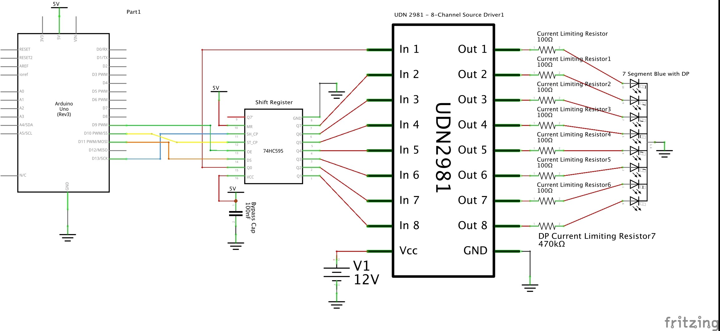
Here is the attachment version of the circuit. How does it look?
Thanks again everyone for your great help!!
Looks good to me but then what do I know ?
Feddar:
Here is the attachment version of the circuit. How does it look?Thanks again everyone for your great help!!
The UDN chip is huge compared to the rest of the components. Do you work for their sales department? ![]()
Let's hope their sales peoole don''t get their training here.
aarg:
The UDN chip is huge compared to the rest of the components. Do you work for their sales department?
Funny.
Ok, I'm going with this circuit. I'll order the parts tomorrow.
Thanks again!
Consider MIC2981 also as UDN2981 is not generally available anymore.
CrossRoads:
Consider MIC2981 also as UDN2981 is not generally available anymore.
Power Distribution Switches, Load Drivers | Power Management (PMIC) | Electronic Components Distributor DigiKey
I did see that UDN2981 was not available On Digikey. Thanks for the suggestion of the alternative. Is MIC2981 much different from UDN2981?
I did, however, find UDN2981 available on eBay. Much cheaper, as well.
Feddar:
Thanks for the suggestion of the alternative. Is MIC2981 much different from UDN2981?
The number is a hint.
The number is a hint.
Oh, you're so subtle... ;D
Paul__B:
What do you suppose the "OE" is for on the 74HC595?
I got my parts, and hooked it all up, and it all works great! Thanks!!
I just can't figure out how to PWM the OE. Could someone please help me with this?
Output Enable.
It enables/disables the output stage.
If you use a PWM pin to drive OE, you can control perceived brightness.
The rest of the chip is not affected by that.
Leo..
I am finding that as the brightness of the lit segments lower, the unlit segments are getting brighter.
Are you using that UDN2981 driver chip.
Maybe it doesn't like floating inputs.
Try 10k resistors from a few inputs to ground, and see if those unlit segments stay off.
Leo..
The 7-segment display I have needs a 680 ohm resistor, so you have probably wrecked the LEDs. The one you purchased comes from china, so it's probably better to buy something that has more specifications. I have never have good luck with products from china.
Wawa:
Are you using that UDN2981 driver chip.
I am. Love it. It's like the ULN2003, but for common cathode.
Try 10k resistors from a few inputs to ground, and see if those unlit segments stay off.
Good idea, thanks.
Works just fine with the higher resistors. Looks like the display is just fine.
Maybe it doesn't like floating inputs.
Seems like it. When I set the PWM to 252 (quite dim), all the segments are nearly the same dimness regardless of which one I am illuminating.
So, is there another way to control the dimming of the display?