Paul__B:
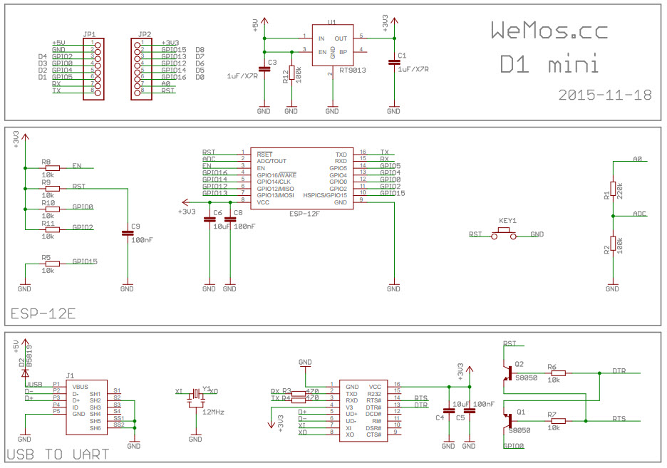
So the proper way is a hybrid of the two. Here is a schematic in which the important data lines are all shown wired, while the various details of the power supply and indicator LEDs require you to "connect the dots". Can't embed it in the post as it is a PDF.Here is another schematic:
Expand!
which is more like yours but a lot more legible, detailing the more functional circuit elements. It is more usable as it does not require as much "connecting the dots" to determine the function.
thanks for the explanation they definitely are a lot easier to read. so the basic idea is to group the schematic into various sections, like all the components associated with USB in one area, all the components associated with the microprocessor in another area etc
attached is a a new version of the schematic, how does that look?

