ClovisN:
@Grumpy_MikeI'll go look up handshaking. Thanks.
Read reply #16 again, I have added some more detail to it.
ClovisN:
@Grumpy_MikeI'll go look up handshaking. Thanks.
Read reply #16 again, I have added some more detail to it.
ClovisN:
Oh, yea... So communication is only possible 1 direction...
No.
ClovisN:
I mean I guess I could run the 3.3V pin on the Arduino to all pins on the Pi that I communicate with and control the logic via transistors... Seems a little convoluted but would that be a safe way of connecting the 2 devices?
That is, as you already noted, overly complex, a simple voltage divider would do the job.
For bidirectional lines you need a more sophisticated level shifter.
Hi,
Do you still have the 1/2second problem?
Can you post your Arduino Tx code please?
Thanks.. Tom.. ![]()
@Whandall and Grumpy_Mike
Yea, I got that bit about the potential divider, but the students haven't learnt about potential dividers yet. Heck they haven't learnt about potentials yet. I'm trying to keep the hardware within the range of what they already know...
Okay, I'll read it once I'm home. Thanks.
I'll post the code once i get home.
Thanks.
Heck they haven't learnt about potentials yet.
So how are they going to understand what a digital signal is?
It seems all to common these days that you teach the "interesting" stuff with no foundation. Then all the kids learn is to follow instructions and not to understand anything.
I have attached the code as a png, coz it was written in drag and drop code. I have also attached the C code generated. I would upload the RPi code as well, except I forgot its not on my system, its on the Pi at the office...
Yea, I agree. But I was instructed to leave out as much of the math and physics as possible to maintain interest in the course. Right now I just explain to them that the pins can act as either the plus or minus of a AA battery and can also check if it is connected to a plus or a minus. It was the best "simple" explanation I could think of.
// generated by mBlock5 for <your product>
// codes make you happy

#include <Arduino.h>
#include <Wire.h>
#include <SoftwareSerial.h>

void sendConfig (){
  // Wait until the Pi is ready to receive data
  while(!(digitalRead(3) == 1.000000))
  {
    _loop();
  }
  // Let the Pi know that the data is ready to be read
  digitalWrite(2,1);
  // Wait until the Pi has acknowledged the data received.
  while(!(digitalRead(3) == 0.000000))
  {
    _loop();
  }
  // Let the Pi know that the next set of bits is being built.
  digitalWrite(2,0);

}

void _delay(float seconds) {
  long endTime = millis() + seconds * 1000;
  while(millis() < endTime) _loop();
}

void setup() {
  pinMode(9,OUTPUT);
  pinMode(8,OUTPUT);
  pinMode(3,INPUT);
  pinMode(2,OUTPUT);

}

void _loop() {
}

void loop() {
  digitalWrite(9,0);
  digitalWrite(8,0);
  sendConfig();
  digitalWrite(9,0);
  digitalWrite(8,1);
  sendConfig();
  digitalWrite(9,1);
  digitalWrite(8,0);
  sendConfig();
  digitalWrite(9,1);
  digitalWrite(8,1);
  sendConfig();

  _loop();
}
It was the best "simple" explanation I could think of.
Pity you couldn’t come up with an explanation that is actually correct, because you can’t actually get a negative voltage out of a pin.
I assume the person who “told” you to do this knows absolutely sod all about the topic. This is what is wrong with education these days.
See if this gives you a better idea about how to think of this
http://www.thebox.myzen.co.uk/Tutorial/Inputs.html
ClovisN:
Yea, I get that. I've read up on it a little. But it seems a little complex for students who don't yet even understand the binary number system.
Perhaps they should take up knitting instead. ![]()
Not sure what you mean by not correct. I get that pins cannot give a negative signal in the sense that they only go from ground to 5V, but really potentials are arbitrary. I could say that ground is now -5V and 5V is now 0V and the physics would work out exactly the same. That's why when communicating between 2 devices a ground connection is necessary for them to work from the same ground right? What matters is the potential difference.
And the people who told me to do this are software engineers who by their own admission know very little about circuitry. They do own the business though, and I'm just an intern so not much I can do about that.
Also, you seem a little angry. Did I break some etiquette? As you probably can tell by my profile, I don't usually post on forums. Then again, I can't really read tone or body language from text so maybe I'm imagining it. Or maybe it's coz your username has the word "Grumpy" in it. ![]()
@Paul__B
I mean, they are 10 year olds whose parents force them into any courses they think will help get the child a better job in the future, so I guess they didn't have knitting as an option...
Not sure what you mean by not correct.
I mean wrong, incorrect rubbish, crap.
but really potentials are arbitrary.
No they are relative not arbitrary,
That's why when communicating between 2 devices a ground connection is necessary for them to work from the same ground right?
Correct.
What matters is the potential difference.
Correct
I could say that ground is now -5V and 5V is now 0V and the physics would work out exactly the same.
Correct, but those statements do not and can not apply together. One of the worst cases of muddled thinking I have come across for a long time.
Also, you seem a little angry.
Yes I am angry that you think you are smart enough to be let loose on 10 year olds to try and teach them rubbish. And I am angry that the people telling you to do this know are so ignorant that they don't even consider what you are trying to teach is important.
You are depriving them of any understanding and just giving them a pile of arbitrary facts to learn with no foundation at all.
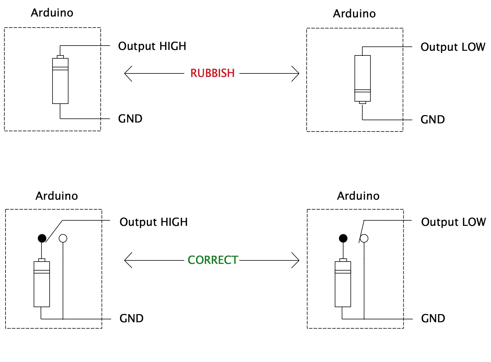
Look at this diagram.
The top two are what you are trying to teach, and the bottom two are what you should be teaching.
Yea, I meant arbitrary starting point. Good catch.
The 2 statements HAVE to apply together right? Otherwise the potential difference changes.
Yea, I understand why you think the analogy is so bad now. You think I'm telling them that the polarity can be flipped. Not really, coz i teach them to treat ground as negative as well.
And yea, I DON'T think I'm smart enough to teach circuitry accurately. I'm still an undergrad and I don't even study engineering, I study physics. But the point is not so much so to teach circuitry but rather spark enough interest so that they learn it in detail by themselves through Googling. Sure they'll end up with misconceptions, but through experimentation and breaking electronics they will learn over time.
You can do some useful work with the students looking at handshaking. Serial (eg rs232 etc) and parallel interfaces eg IEEE 1284 all use either a clock signal or handshake signals to ensure validity of the data.
Well, I talked to my bosses, and they decided that the circuitry required to solve the 3.3V vs 5V difference is too complicated and would rather I just help students setup standard serial connection coz that's good enough for the next part of the course. So I guess I'll have to shelf this idea for now. Thanks for all your help though, I learnt a lot.
You still need a voltage level shifter between the (3.3V) Pi RX and the (5V) Mega TX. A voltage divider is the simplest level shifter.

they decided that the circuitry required to solve the 3.3V vs 5V difference is too complicated
So side step the issue by using an Arduino that runs off 3V3. There are lots of them about. Tell them it is important that two systems work off the same voltage or else they need “complicated” circuits to match the signals.
Yea, that's the general schematic I showed my bosses. They said it looks like too much circuitry. I'll try building it on a breadboard and see what they say I guess.
That's a good idea actually. I'll run it by my bosses to see if they can get the boards. Thanks!