So I have a kit with instructions on how to put it together, but it's designed that you leave the circuit boards exposed and just stand it on them as a way to to expose the soldering and assembling you've done so that it can be easily seen.
I would like to make a little case for this out of balsa wood or plexiglass but that would require making the buttons and Battery connectors a little off of the boards so I can fit the case material around or under them with a space cut out.
Would adding a little bit of wire or a male and female Bridge pin to get this space needed for the casing cause anything I need to be aware of in terms of additional resistance or or the distance a signal has to travel.
Also if I increase the wires engage that came with it by one or two sizes in thickness would that also have things I need to worry about, because the only wires I have are the thickness of wire for a standard solderless breadboard, and some of the wires in this kit are the thickness of the metal itself of these wires but with a plastic are so delicate just trying to use my plastic cutter thing with a little holes down the edge for size you sent the pull one size bigger than I'm supposed to use as well as using the hole I'm supposed to use just rips the wire and two when I pull it.
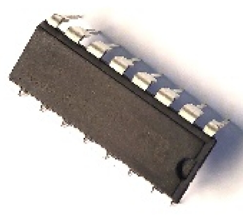
And lastly the IC microchip is showing to just solder directly to the board, is it fine to buy a mounting thing that I saw on other module's in its place so that this can just clip on?
So for all these little quality of life edits, is there anything I need to confirm before trying in terms of the way current flows or the resistance or any other factors I may not be aware of that may pop up from adding such change?
I'd be happy to offer advice, but I feel that it would be more productive and a more efficient use of my time, and the time of other helpers, if you could narrow the generalizations to the specific board(s) and device(s) that you actually have. Please post details.
The resistance of wires only becomes significant when they are carrying large currents - with buttons, indicator LEDs, displays etc it's not going to be significant.
Places where it does get significant include power supplies to:
Motors
Radio modules
Relays & solenoids
Making wires thicker won't hurt; making them thinner will only matter in (relatively) high-current uses
It's called an IC Socket. They come in various sizes & configurations and you'll have to match the package type. But for a 'high density" chip you might not find one.
When it's practical, I like using sockets... If you have a problem it's easy to swap-in a new chip. That can be handy even if you're not sure if the chip is the problem because you can swap-in a new one to find out. (And I always try to have extras of everything whenever possible.)
You can "extend" switch & LED connections with wires but if you go several feet the wires on inputs might start picking-up noise. Of course, you'll generally need to solder and some heat-shrink tubing gives a nicer "finish" and adds a little mechanical strength and helps to prevent shorts.
The wire thickness (gauge) isn't critical. It should be thick enough that it doesn't easily break but not too thick to work with. 22AWG is "about right" for most electronics situations.
Stranded wire is more flexible and generally easier to work with than solid wire, but if you have a plug-in breadboard you can't directly plug-in stranded wire.
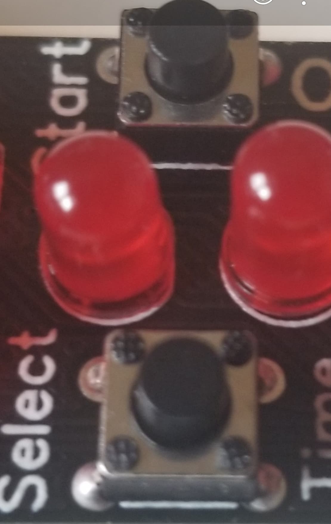
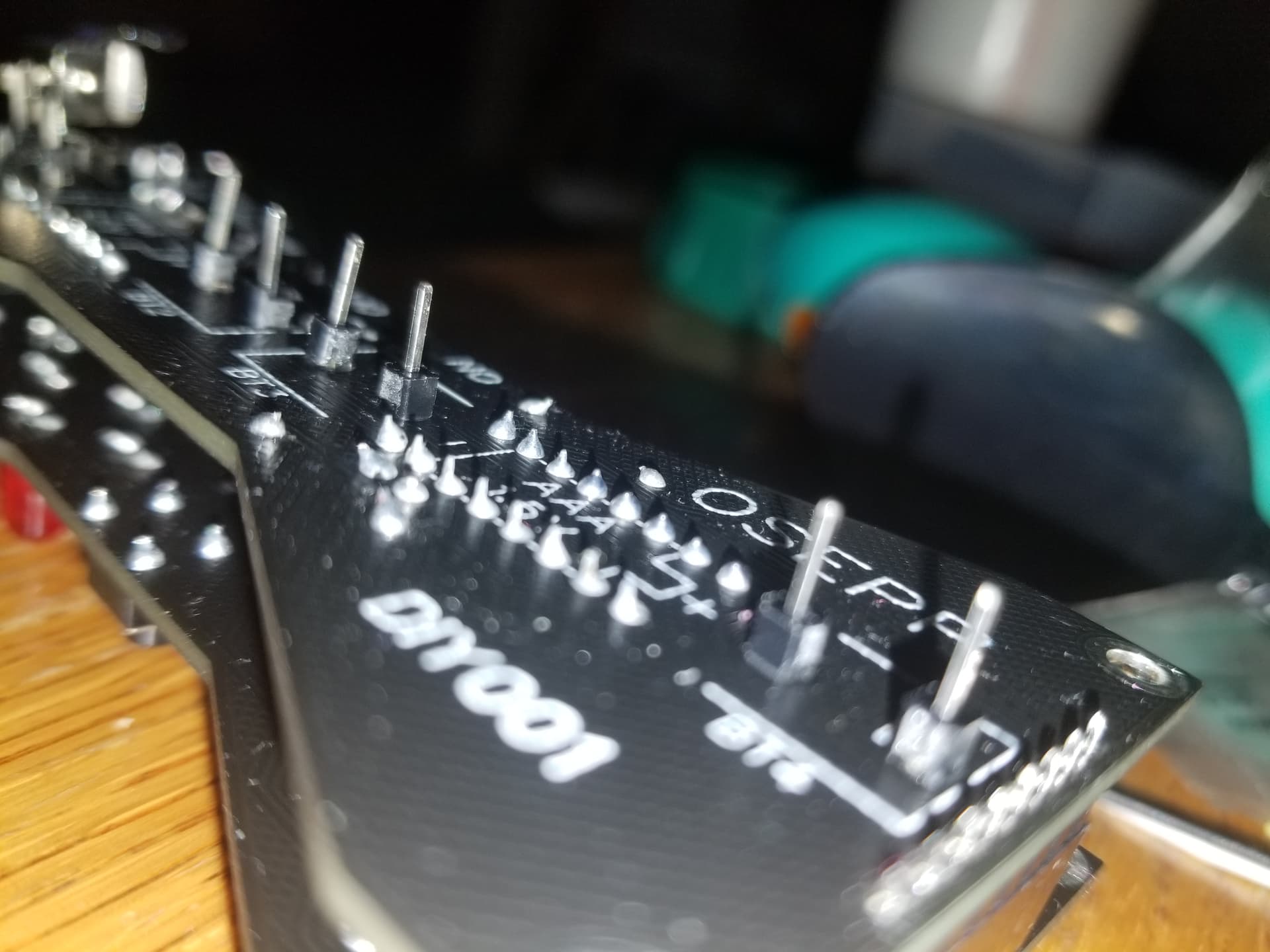
i ended up just mounting them directly, and ill make a long plastic peg to push button for the case instead.
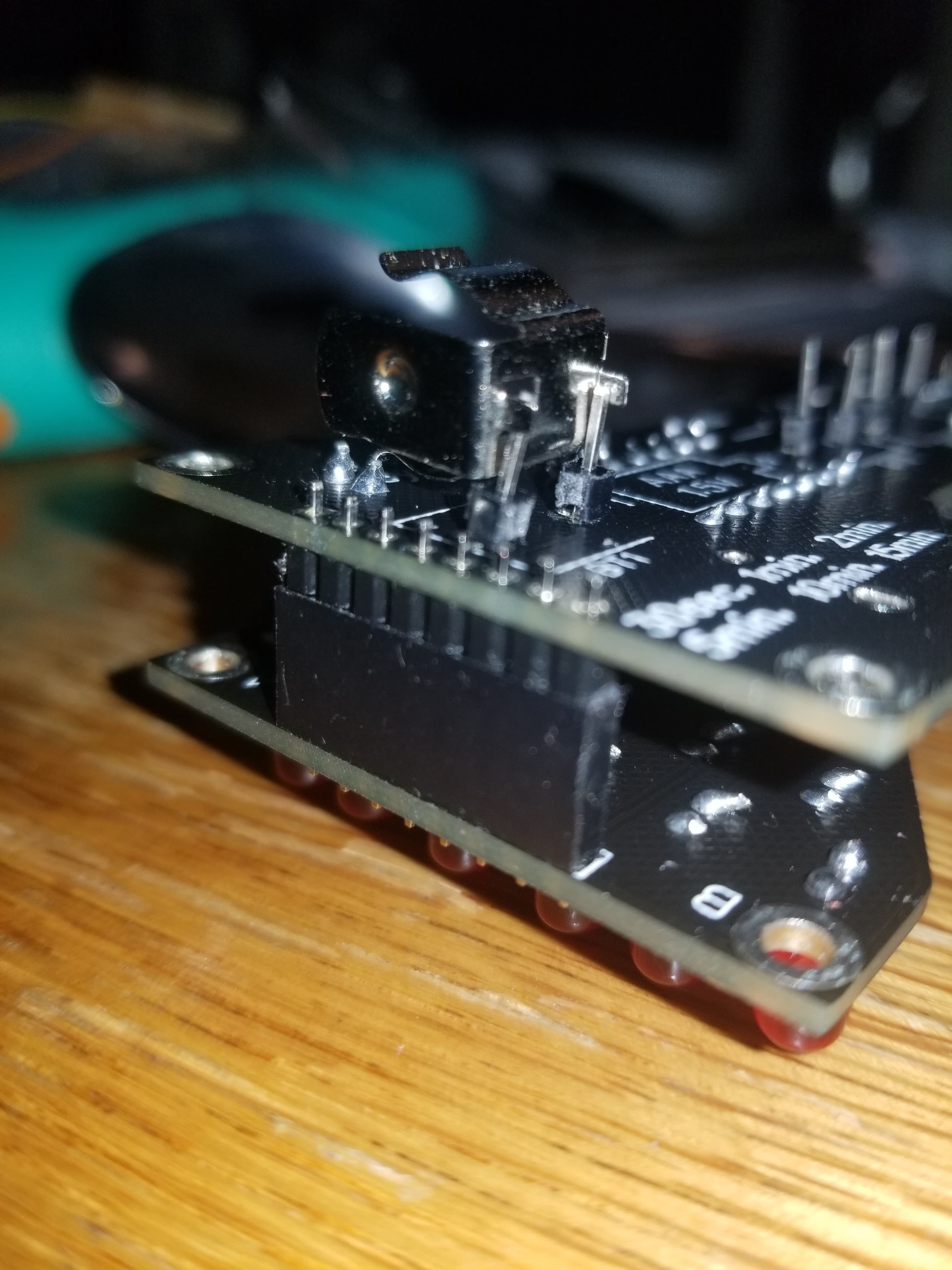
But if i put thise on pin headers so they were 1/2 -1 inch off board is whst i was meaning.
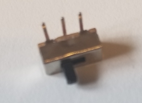
This one i wanted extended again same way, but will do the plastic peg on the switch instead.
Would still like the info on that edit to these for later projects.
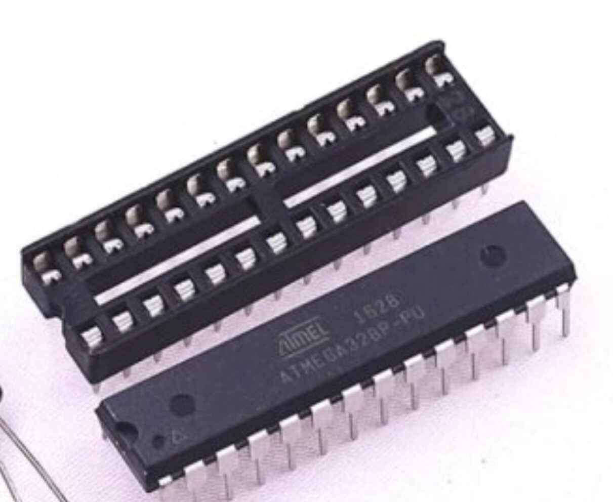
That part the IC goes into.
Im assuming they come in all possible IC shapes? Does using one of those affect the circuit differently than when you sauder it right to board i had meant.
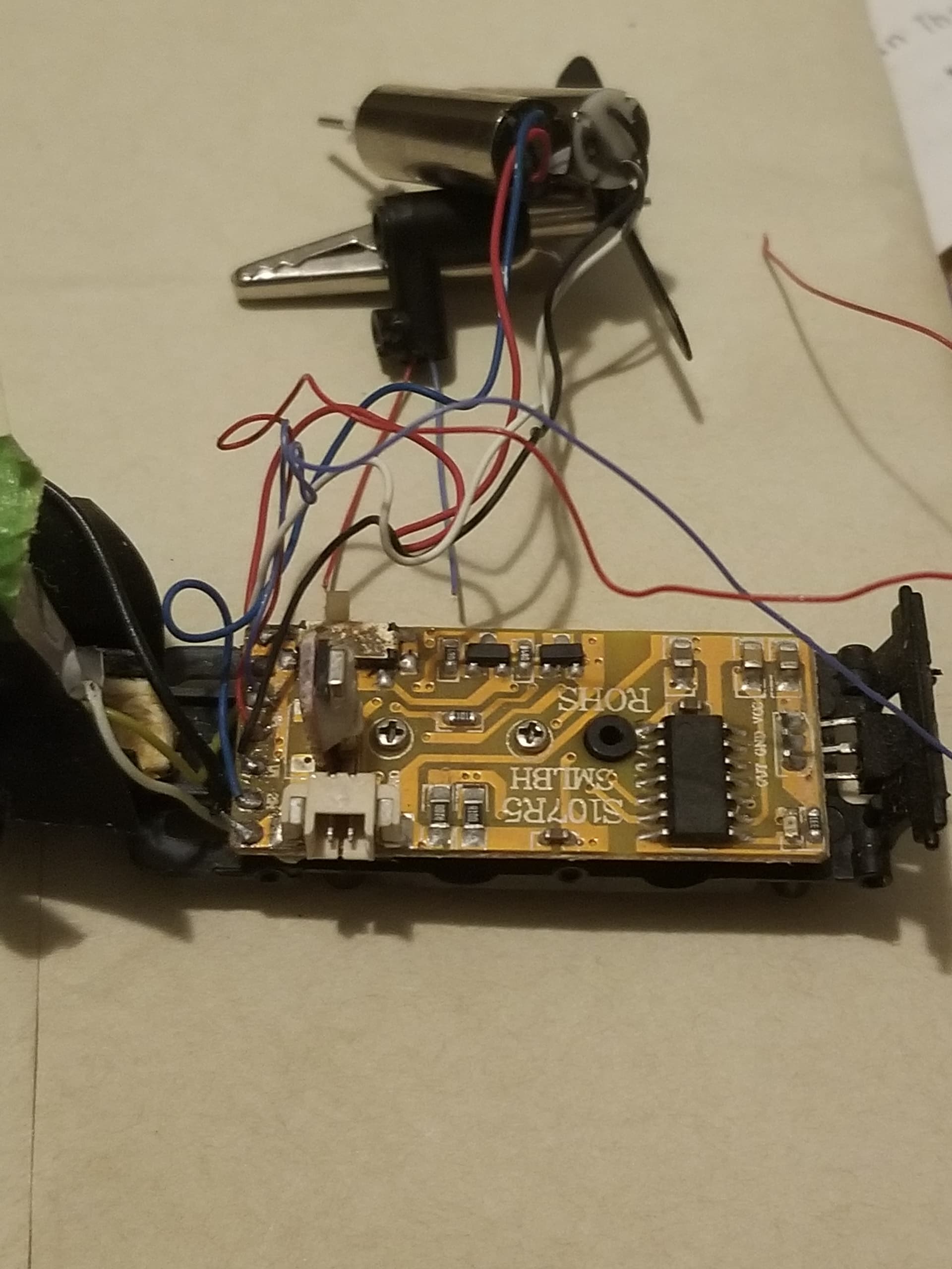
The wire thickness question was for this, it was an older cheap rc heli.
I want to remove 2 of 3 motors, and fix it to a styrofoam glider (about 12 inches long) so it can hang from roof by a string and just use the remote made for it to turn a airplane propeller motor type of direction to mount it so it makes itself fly in a circle.
Trying to just move the wires to see what they run to makes them snap they are soooooo thin.
So i wanted to use my arduino breadboard wires to swap in so they can be a bit tougher to break.