Advice on Mosfets

Hi all

I have an upcoming project, and I wish to use Mosfets... something I don't tinker with very often.

The requirements will be for a Pro-mini or similar to control pairs of outputs at +24v 4A.

Here is the twist. These outputs need to isolate from the supply entirely when off, so a P-Channel for the +24v and an N-Channel for the 0v.

Now in an ideal world, these outputs would have the ability to be reversed, but I'll try to walk before running.

Try as I might, I have real issues trying to understand how you calculate this stuff.

I found this image of a P-channel. Suitable? (fills me with fear having the +12v rail on the 5v pin - yes, keep the grounds apart).

I actually like the idea of isolating the Arduino using opto-couplers. I have loads of those lying around
P-channel-high-side-switch

As for the Mosfets themselves.... apart from literally every item in RS/Farnell and Digikey being out of stock, I found these..

https://uk.rs-online.com/web/p/mosfets/6710949
https://uk.rs-online.com/web/p/mosfets/6710936

But... with 2434 to choose from after narrowing down some of the specs... where the heck do you start!

I could achieve it with relays, but that is expensive, unwieldy and noisy.
Any pointers would be oh so very gratefully received.
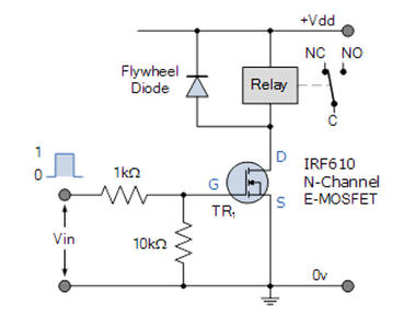
  • I would use an N-channel Mosfet with the source grounded and the load in the drain circuit.
  • Then I would move R4 to ground instead of +V and swap the opto output and R2.

The reason for opting for the N-Channel is the semi construction is simpler, has better heat dissipation and a lower ON resistance ( with all other things being equal).
They should be easier to find as well.

Digikey seems to have plenty of N-Mosfets Table link

Don't be afraid to purchase one with a much greater current capability than your current project requires

Why does it have to be a P-channel? And, why would a common-ground be a problem?

mosfet switch

It doesn't keep the grounds apart, you are making the common mistake of assuming that the negative terminal is always ground / 0V. The circuit you have makes the positive of the 5V and the positive of the 12V into ground and 0V, so the supplies become -5V and -12V. Nothing wrong in principle but the Arduino boards are designed with the negative as ground, not 5V. The problem you now have is if you connect the USB port to the computer you have -5V on what the computer thinks is ground. If you connect your now positive ground to actual ground you will be shorting out the 5V supply.

Your circuit can work, but you need to be really careful.

Final point is that I sense that people think ground has some mystical status that makes it work differently to other voltages. 0V is a point defined in the circuit by the designer. Ground is generally 0V and is the common point between different parts. Apply normal circuit rules to it.

Oh dear!

10k resistor in the wrong place!

It will work either way. The purpose is to pull the gate low when whatever is driving it floats.

The IRF610 is not a logic level MOSFET so you can't drive it directly from an Arduino pin. It also has a 3.3A continuous current rating which is lower than OP specified.

OK here it is drawn...

image

It wasn't meant to be a solution- just an example of high-side load control.

Which actually makes the mis-placement of the 10k resistor more of a problem. :grin:

Missing the current limiting resistor for the opto-coupler.

Good catch, however I didn't add it in on purpose as I don't know what opto is being used or if they want it a pull down or pull up. I only added the two grounds to show they were separate.

Yes, those images were just Googled examples. Not the actual components I intended to use.

Those components I selected (rightly or wrongly) are over-spec with regards to the amperage.
For once, my PCB has lots of space.

I wasn't saying the grounds were apart in that image, I was saying that if I linked them by accident, smokey things will occur.

I am trying to replicate a fireworks trigger unit PCB I have here from many moons ago. You connect the fireworks (small ones) across the 24v terminals and you can remotely fire them.
This PCB does that wirelessly, but I don't need that function.

I remember the old controller (which never worked properly and the LCD screen is missing) had the ability to have either common ground or separated grounds. For fireworks, you would use common ground.

But if you use the controller to actually run individual pieces of kit instead of Fireworks, they recommended separated ground. I wanted to add that as a feature just because I can.

The old controller is a broken old thing with all the Mosfets and IC identifications sanded off. No idea what they are.

The 0v pins appear to be switched with a standard N-channel Mosfet.
The +24v pins are actually connected to (what I believe to be) a dual channel P,N Mosfet.
It is a 5 pin Mosfet style device and all I can make out on the top is '- | + S O'.

First pin is to ground (-) and the 'O' pin goes to the output.
I think the second pin '|' is the gate.

All the mosfet tabs ('+' pin) are switched through another master Mosfet, so that isolates the whole row of +24v from what I can tell.

My only reasoning for this dual channel Mosfet (if that is what it is) might be that you could originally add a board to this to switch more channels (no idea how many). Therefore I assume this was to maybe multiplex the outputs? Who knows. But, I don't need that function for my little home project.

As for using a P-Channel. I wanted to switch the +24v, otherwise the attached item always has +24v attached an I was trying to achieve total isolation (or as near as possible).

Just thought it was an interesting Crimbo project.

That tells me you've not understood what I said. There are not 2 grounds in the image that cannot be linked. No you can't link what I think you are calling grounds, but at least one of them is not ground. Here's another way of looking at the same thing:

Referring to the top image in reply #1: Keeping ground as what Arduino designed it to be, the negative terminal of the supply to the Uno. You have the positive of the battery marked as 12V, this is misleading, yes it is a 12V battery but that point in the circuit is not +12V. That point is connected to the Arduino's 5V connection, so that point is +5V. The negative terminal of the battery is then 12V less than +5V, so -7V. No where in the right hand side of the schematic is anything connected to ground, not the MOSFET, the motor or the battery. No part of that bit of the circuit can be considered to be ground. You can't connect the negative of the battery to ground because it is 7 volts below ground.

OK. Understood. I do understand Perry. I have learned to take Googled circuit diagrams with a degree of suspicion.

I meant, to just gleefully connect that 'black' minus terminal (that is -7v) on the right to my 0v rail on my breadboarded Arduino.

Thanks for the advice

Why do the resistors used to supply the gates of these Mosfets vary so much? I assume it isn't that critical? Seen some at 100R, some at 1k and some at 10k.

I was planning on 1k, held to the relevant rail (high or low) with a 10k.

Why do my projects always get far more involved than I anticipated? Lol

This PCB has a connection to a pair of 12v 2A Lead acid batteries connected in series to provide the 24v. They appear to actually still be good.
There is also a charger that provides 18.4v DC, but I just cannot decipher the charging circuit on the PCB

Now charging batteries is a dark art to me. I have been a Googling again. From what I read, the charge voltage should be 28.2v - 29.4v for 24v Lead acid? But it must have used the 18.4v, so that info must be/might be wrong.

Obviously I need a charge circuit for this (not just stuck directly on a supply).

tn_lead-acid-battery-charger-circuit

Would this circuit would seem suitable (yes, I know it show a 12v battery)? As I imagine I can then adjust my charge current.
But I know its not as simple as that.

Because the exact value is not critical*, some people leave them out altogether. I would say that about 220Ω is reasonable, as that will limit the current from the pin driving the MOSFET to just over 20mA, so will not overload it.

MOSFET gates are low value capacitors, so at high frequency they look like short circuits. When the pin changes state there is a very brief pulse of current to charge / discharge the gate capacitance, the value of this current can easily exceed the maximum allowed for the pin. However, it is for a very, very short time period so whether it can actually do any damage is up for debate.

If you want MOSFETs to switch really quickly then you need a gate driver, which is just something that can source or sink the required currents to charge and discharge the gate really, really quickly.

*As an aside the person who taught me C struggles with this concept. He asks me why component values are not critical, he never really gets it. He is used to software where a single character out of place messes up the code.

2V2 per cell is fine for a lead acid battery, so for 12 cells 26V4. The voltages you quote seem too high to me. However, there is a lot written about lead acid batteries and it depends what you are trying to do. If you want to quickly charge a flat lead acid battery then you can use the higher voltage, but not indefinitely. If you put 2V2 per cell across it then it will charge and you can maintain it like that. 2V2 per cell is good for standby use, you have a PSU that can supply the whole load at that voltage and you just put the battery across the output of the PSU, with the load across both. You MUST include a fuse in the battery circuit, for 2 * 6 cell batteries in series I suggest putting the fuse in the wire that links them. A lead acid battery can easily produce enough current into a short circuit to start a fire.

The circuit looks fine but I don't see the point of the current sense circuit (BC548, 0Ω5 and 100Ω) because the LM317 has built in over current protection.

Thanks for the advice Perry. I hate asking these questions, but hours and hours of Googling and reading is no substitute for someone with knowledge.

Plus, there are a lot of 'dud' circuit and incorrect information splattered over the net these days.

I have a fuse in my planned circuit for the batteries. The battery pack here are linked directly, but I can always change that.

The plan is to trickle charge only. I don't think fast charging will be needed.

I wish I could get my head around all this stuff, but it just doesn't sink in when I try the 'mathematical' approach.
I bought a massive book a while back that basically showed you everything to do with the calculation side of all things electronic. My brain just imploded after an hour.

Then 2V2 per cell, connect and forget. Possibly up to 2V3 per cell but no more.

If you understand Ohms law and Kirchoff's circuit laws, and the relationship between voltage, current, resistance and power, then between them they will answer a lot of your questions if you apply them. Those are essential. The other stuff you can learn if you need it.