Hi,
I am a beginner and I am working with 74hc595 shift register the problem is that
all of my leds does not glow at the same time when I program them to glow only few light up brightly and few glow very dim and few does not glow at all.All of my leds are good I checked them by replacing the non glowing leds with the glowing leds which is connected to the shift register I just replace their position and the non glowing led glows.
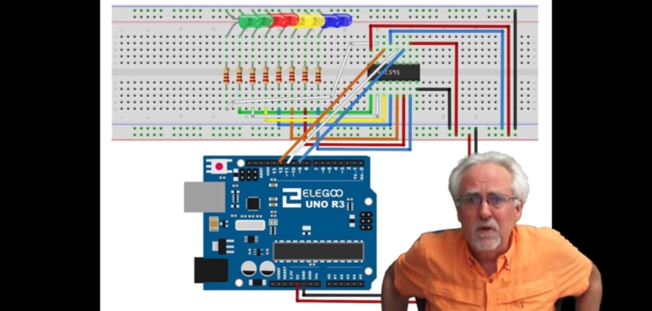
I gave my circuit in the following attachment.
And my code is
Int latchpin=11;
Int clockpin=9;
int datapin=12;
byte LEDs=0xFF;
Void setup(){
pinMode(latchpin,OUTPUT);
pinMode(datapin,OUTPUT);
pinMode(clockpin,OUTPUT);
}
Void loop(){
digitalWrite(latchpin,LOW);
shiftout(datapin,clockpin,LSBFIRST,LEDs);
digitalWrite(latchpin,HIGH);
}
Some breadboards have split power rails, indicated usually by breaks in the red and blue lines that run along side these. This could be the problem here.
Thanks sir
I placed the chip very carefully and done it twice but same result.
But eventually I supplied external voltage to my circuit and my first and last two leds out of 8 leds does not rest glowed very fine. Now I can't understand what to do.
You need a 0.1uF ceramic capacitor connected across 5V and GND close to the chip. This is called a "bypass capacitor" and is needed for all chips. Without it, the chip may not behave correctly.
No, it isn't. Please post the code you are actually using. The code you posted would not compile/verify. For one thing, "Void" and "Int" would cause error messages. C language is case-sensitive and will only accept "void" and "int".
Thanks PaulRB
Sorry for (Int) I made this mistake will posting in forum but I had put( int ) in code and it compiled very well and the chip also functioned according to my code but the problem is all my leds does not glow properly only some glows and those show the correct behavior but don't know why the rest leds does not glowing.
Ok, we believe you about how your code looks and we forgive you for posting different code in your first post.
But please never post photographs or screen capture of your code in the IDE again. That will make many forum members quite angry. You know how to post code correctly on the forum, using code tags, so please always do that. But never try to post code by re-typing from memory, because you will make mistakes and we will spot them.
Your code looks ok. So maybe the problem is the circuit. What about my suggestion from post #4? A bypass capacitor is not really a suggestion, it is mandatory. There is no point wasting time trying to figure out what problems there may be, if your circuit does not have bypass capacitors.
Of course you do not get the colour mark-up when you post using the "code" tags but that is not particularly important; just a little convenience in the IDE.
This is particularly puzzling. The fact that code repeatedly re-writes the data to the shift register at a ridiculous rate should not cause the odd behaviour, but after you have added the 0.1 µF capacitor directly across the 5 V and ground pins of the 74HC595 and tested that addition, next add a "delay(1000);" to your loop() code.
I applied a 100 micro farad electrolytic capacitor directly to the 5v and ground of the circuit and used 80 ohms resistor for leds .
But now I can't even turn on one led .Also I changed the chip but same result.
ravirao8896:
I applied a 100 micro farad electrolytic capacitor directly to the 5v and ground
That is a good thing to have. But you still need the capacitor of the type and value I mentioned before. It may not fix the problem, but it is needed, always.
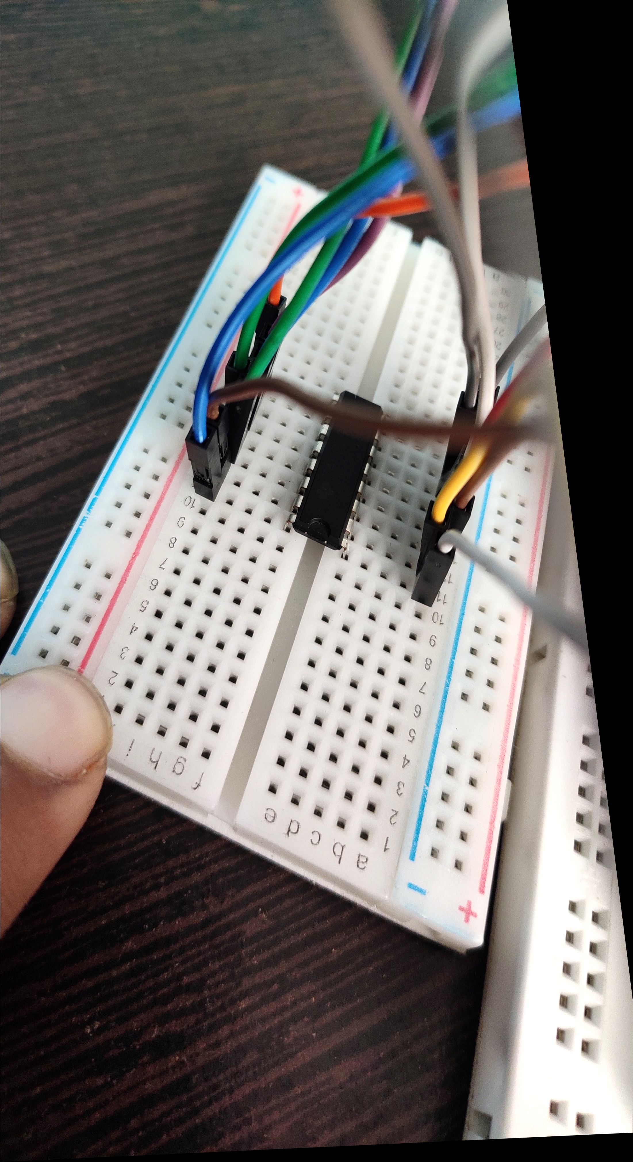
If you still cannot make it work, post some bright, clear, close-up photos of your circuit so we can see how everything is connected.
Today I replaced some non working leds with new one and used other breadboard and all leds light up .
But they do not shut down as I code them to by making byte LEDs= 0x00 (leds) in my code .It does not even responding now to my code. The leds now just keep glowing and does not get effected by my code.
And I also attached the photo of my circuit I attached.