Need a better op amp. One with Rail to Rail output, will give bigger output swing.
What are you using for the resistor divider? Is that drawing a lot of current?
Need a better op amp. One with Rail to Rail output, will give bigger output swing.
What are you using for the resistor divider? Is that drawing a lot of current?
It should draw less than 1mA.
I'm using one 1,54khoms and one 6,67khoms. (I changed my setup in the first picture.)
What do you mean by giving me a better output swing?
MaxiMax07:
What do you mean by giving me a better output swing?
in voltage follower mode, (where the input voltage is connected to the +IN, and -IN is connected to the output) the output of a rail to rail op-amp will go from V- to V+. Your LM358 will follow from ground up to about 4 volts, then anything from 4 to 5 volts will still output 4 volts. A rail-to-rail amp (like this one) will go ground to 5 volts.
The range of output voltage, compared to the input voltage is called the output swing.
ps, the letter V in an op-amp's name usually means that it is a rail to rail device.
Did you try 10x the value of the voltage divider resistors using the arduino 5V ? (15.4 k & 60.6 k) Can you measure the current drawn from the arduino 5V pin when it does NOT work cirrectly ? ( using a DMM)
MaxiMax07:
Hi,I really need your help! I never used a breadboard and neither a amplifier operational of my life.
However I need one to compare a voltage.
To compare voltages use a comparator, not an op-amp. The quad comparator LM339 is very
cheap and a good all-round device. Like most comparators its output is open-collector so you
would use pinMode (..., INPUT_PULLUP).
Its inputs are rail-to-rail and it works from any supply in the 2V to 36V range.
Some opamps are not suitable as comparators as they cannot tolerate large voltage differences
on the inputs, and most are very slow compared to real comparators and can cause multiple
logic transitions without a schmitt-trigger input to clean up the ouput.
Good point. Op amps are great for just about everything but when it comes to comparing voltages, dedicated Comparators like the LM339 are better , and because of the open collector design, they are by definition RAIL-TO-RAIL. (and then there's the fact that they cost maybe 1/10th the price of an op amp. Op amps and dedicated comparators make a great combination.
MaxiMax07:
Thank you! I just need to add the capacitors!However I got some news! For a reason I TOTALY don't understand, when I using the 5V pin of the arduino, it doesn't work, but when I use a 5V battery. It works! Why?
The headroom is about 1.3V thought. Seems big.
The capacitors are the decoupling capacitors i mentioned earlier.
5V pin of arduino should work but one of the things the decoupling cap does is reduce interference from digital noise.
A DMM will not see that.
The implication is that the problem lies with the supply somewhere.
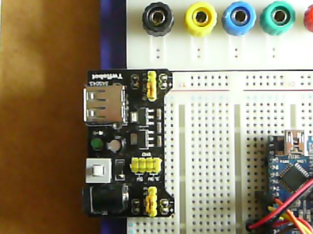
Photo is a supply i use for prototyping digital stuff.
I had a similar one for dual rail OP amps which i had to discard as it caused toomany problems even with copious decoupling
I have gone back to using a couple of PP3 and everythink s OK
The implication is that the problem lies with the supply somewhere.
The capacitors are the decoupling capacitors i mentioned earlier.
I never used a breadboard and neither a amplifier operational of my life.
We tend to throw around terms we are familiar with and often forget that newbies don't understand the theory behind it.
CAPACITIVE REACTANCE = 1/[2Pif* C] | where "C" = Capacitance (in Farads (F))
"f" = Frequency (in Hz)
"Pi" = Apple (slices) (just kidding! Pi= 3.14159265359)
So , if someone in this post recommend 0.1 uF (AKA 100 nF) decoupling caps (typical value), then :
in order to calculate the reactance , you need to select a frequency (in Excel you could plot the frequency with respect to reactance or vice versa, as the reactance is a function of frequency. SEE ATTACHED) That being said, there is no single frequency of interest when discussing decoupling caps, (unlike calculating a LOW PASS FILTER where you have a specific cutoff frequency in mind)
Let C = 0.1 uF
f = 1000 Hz,
XC = 1/[23.141592653591000*0.1 E-6]
= 1 /[6.283185307179586476925286766559e-4]
= 1591.5 ohms
Let f = 10,000 Hz
XC = 1/[23.1415926535910000*0.1 E-6]
= 1 /[6.283185307179586476925286766559e-4]
= 159.15 ohms
Let f = 100,000 Hz
XC = 1/[23.14159265359100,000*0.1 E-6]
= 1 /[6.283185307179586476925286766559e-4]
= 15.915 ohms
So you can see, as f increased XC decreases, approaching a short
The result is that a very short duration spike is shorted to GND.
OP
Using the link you provided.
I built your circuit and had it working ok, which had me somewhat baffled.
Re reading it appears you are using a different IC , this detail is important.
Elsewhere others have explained some of the reasons why.
It has also become clear that you can understand a schematic.
Fritzing diagrams can be annoying.
Hand drawn circuit , uploaded as a photo is a far better way of communicating to the forum.
Using the link you provided.
FYI, COMPARATOR is Figure 29 on page 18
Thank you for all your answers! It actually give me the answers of some questions I would of ask this morning.
First of all, I'll explain where I am now with this circuit:
My circuit has for goal to translate the analogue output of my wheel encoder to an digital output. It started working when I used the battery as supply and still doesn't work with the 5V arduino pin. So the translater works when I'm turning my wheels by hand. I'm very happy. However, when I use the motors and the speed isn't really slow, I start to have a lot of false reading to the point of when I told the robot to travel 1m, he does like 7 cm.
I thought I'll do a Schmitt Trigger this week-end because maybe it's the noise that do this issue. However, you seem to think it's the op amp that isn't suited to do this job. I should first of all get a comparator and then see if I need to do a Schmitt Trigger? Also I should pick up the capacitors for the supply of the comparator?
Now I'll try to answer every post:
in voltage follower mode, (where the input voltage is connected to the +IN, and -IN is connected to the output) the output of a rail to rail op-amp will go from V- to V+. Your LM358 will follow from ground up to about 4 volts, then anything from 4 to 5 volts will still output 4 volts. A rail-to-rail amp (like this one) will go ground to 5 volts.
The range of output voltage, compared to the input voltage is called the output swing.
ps, the letter V in an op-amp's name usually means that it is a rail to rail device.
If I understood well, I should try to by a follower comparator because it fits the alimentation I give it (5V and GND).
raschemmel:
Did you try 10x the value of the voltage divider resistors using the arduino 5V ? (15.4 k & 60.6 k) Can you measure the current drawn from the arduino 5V pin when it does NOT work cirrectly ? ( using a DMM)
My DMM can't mesure a current under 0,9A so I can't ![]()
I didn't tried with that, but I tried another arrangement with others resistances and I had the same issue.
Boardburner2:
The capacitors are the decoupling capacitors i mentioned earlier.5V pin of arduino should work but one of the things the decoupling cap does is reduce interference from digital noise.
A DMM will not see that.
The implication is that the problem lies with the supply somewhere.
Photo is a supply i use for prototyping digital stuff.
I had a similar one for dual rail OP amps which i had to discard as it caused toomany problems even with copious decoupling
I have gone back to using a couple of PP3 and everythink s OK
Photo is a supply? What do you mean?
So you are telling me that I can get some interference from the reactance? I didn't know that, I thought it would only make me have a bigger electric bill.
Thank you for the explanation raschemmel! It's hard to know what you guys talk about sometimes because I studied it in french one year ago. We don't have the same keywords and it's been some time. However, one thing I don't understand. Why do you calculate all those frequencies? I had to do this kind of calculs with motors to know there efficiency and we always used the frequency of the supply, so 60 Hz. The "noise" is some frequencies in the reactance?
Boardburner2:
OPUsing the link you provided.
http://www.ti.com/lit/ds/symlink/lm158-n.pdf
I built your circuit and had it working ok, which had me somewhat baffled.
Re reading it appears you are using a different IC , this detail is important.
Elsewhere others have explained some of the reasons why.
It has also become clear that you can understand a schematic.
Fritzing diagrams can be annoying.Hand drawn circuit , uploaded as a photo is a far better way of communicating to the forum.
I don't know what a IC is.
Okay next time I'll try to make a schema like raschemmel and CrossRoads did!
MaxiMax07:
Photo is a supply? What do you mean?So you are telling me that I can get some interference from the reactance? I didn't know that, I thought it would only make me have a bigger electric bill.
I don't know what a IC is.
Its a power supply i use for breadboard use, dual rail selectable voltage, Linear.
The +- v one was a switching supply which generated too much interference for op amps, ppp3 better.
When a digital circuit like an arduino switches an output the fast switching time puts a sudden load on the supply. This can cause a spike on the voltage as even pcb traces have inductance at high speed.
A cap close to the chip helps to kill this interference.
IC is an Integrated Circuit.
I don't know what a IC is.
Oh boy. We have our work cut out for us.
"IC" stands for INTEGRATED CIRCUIT.
I did all those calculations to show you how reactance affects high frequency noise.
The purpose was to teach you that the higher the frequency of the noise, the lower the resistance (impedance) of the reactance of the capacitor, and the faster it is shunted to ground.
in voltage follower mode, (where the input voltage is connected to the +IN, and -IN is connected to the output) the output of a rail to rail op-amp will go from V- to V+. Your LM358 will follow from ground up to about 4 volts, then anything from 4 to 5 volts will still output 4 volts. A rail-to-rail amp (like this one) will go ground to 5 volts.
The range of output voltage, compared to the input voltage is called the output swing.
ps, the letter V in an op-amp's name usually means that it is a rail to rail device.
If I understood well, I should try to by a follower comparator because it fits the alimentation I give it (5V and GND).
NO NO NO.
You are not even in the same ballpark !
"Voltage-follower mode" is one of MANY op amp configurations. We can't teach you electronics in one post. You have to google things (like op amp voltage follower) and read up on it.
What he was trying to tell you is that if you wire the op amp in a mode where it is supposed to follow the input voltage EXACTLY, it CANNOT because it is NOT a RAIL TO RAIL op amp. If your task is to compare voltages, you can use a COMPARATOR which is an IC (remember Integrated Circuit ? that's the fancy name for a chip). A COMPARATOR is a chip made specifically to do one thing and one thing only, which is to compare voltages and it is designed as an "OPEN COLLECTOR OUTPUT" (Google it) so you need to either put a real physical resistor from the output to +Vcc (5V) or you need to configure the arduino input as input pullup.
To compare voltages use a comparator, not an op-amp. The quad comparator LM339 is very
cheap and a good all-round device. Like most comparators its output is open-collector so you
would use pinMode (..., INPUT_PULLUP).
The photo Boardburner (what a handle !) posted was a small pcb mounted regulator , similar to these:
His point was, that kind of regulator generates NOISE the decoupling capacitors shunt that noise to GND.
I have no idea why you are talking about your electric bill going up. You lost me with that comment.
You talk about schmitt triggers but you don't know what an IC is ?
What's the story ?
I had a course in electronic at the uni, so I know about theory and some circuits. But I never applied any knowledge, I don't know the rail to rail thing. I just learned basic theory of electric engeneering so I could understand what an electrician is telling me or if I work with motors. (I'm studying in mechanical engineering.)
With a previous post on the forum, they proposed me to do a Schmitt Trigger and I read about it on the net. However with the advice of a friend in electric, I tried to do a simple comparator first to see if it could work. (He told me I didn't need to do a Schmitt Trigger.)
I don't know what an IC is because I always studied in french. All the acronyme you use I don't know them. Often I find them on google. But IC is too general, I found nothing.
Okay I understand. It's just that I never studied noise or any real application in electric.
How do I shop a comparator? I'm looking to some datasheet and there are too much information as in the datasheet of the [LM339](http://www.ti.com/product/LM339) you told me to check out. I tried to check for comparators by myself. I found the LMV339, LMV393 and TLC372 quite suitable I think. I'm not sure because I don't understand all the terms in the description. Do you think my first choice, LMV339 is suitable? Is it a bad idea to take a "low voltage application" feature?If there is a lot of reactance made by motors and wires let's say in a factory. Its consommation of power goes up. So you put "decoupling capacitor" for the reactance to go down so the kWh drops.
raschemmel:
The photo Boardburner (what a handle !)
My first arduino project was a soldering oven.
I forgot to put the thermistor in the oven.
Second attempt i remembered the thermistor but forgot the first run was in teach mode, and did it again.
Since then i have had some spectacular results from multi Kv pcbs as well.
MaxiMax07:
How do I shop a comparator? I'm looking to some datasheet and there are too much information as in the datasheet of the LM339 you told me to check out.If there is a lot of reactance made by motors and wires let's say in a factory. Its consommation of power goes up. So you put "decoupling capacitor" for the reactance to go down so the kWh drops.
The LM339 is a good starting point, it's common and cheap.
Reading and understanding datasheets needs practice and experience.
As far as reactance of motors are concerned.
Power factor correction is important in industry for lower bills.
It's not really an issue at electronic power levels.
In this application the capacitor is not acting as a decoupling capacitor.
Inductance and capacitance are however very important.
Boardburner2:
The LM339 is a good starting point, it's common and cheap.Reading and understanding datasheets needs practice and experience.
As far as reactance of motors are concerned.
Power factor correction is important in industry for lower bills.
It's not really an issue at electronic power levels.
In this application the capacitor is not acting as a decoupling capacitor.Inductance and capacitance are however very important.
I bought the LM393 because they only had this one at the shop and it's the same but with dual channel instead of four. However my circuit stops working now. I have reading jumping at the roof. Do you think it's due to the noise? I couldn't get a capacitor today because they didn't had any that work with 5V. I'm thinking about making the Schmitt Trigger, But maybe I'm missing something. I changed nothing in my circuit (according to the datasheets, it's the same pin at the same place. I only changed input by input_pullup.
MaxiMax07:
I bought the LM393 because they only had this one at the shop and it's the same but with dual channel instead of four. However my circuit stops working now. I have reading jumping at the roof. Do you think it's due to the noise? I couldn't get a capacitor today because they didn't had any that work with 5V. I'm thinking about making the Schmitt Trigger, But maybe I'm missing something. I changed nothing in my circuit (according to the datasheets, it's the same pin at the same place. I only changed input by input_pullup.
Try running it from a PP3 battery rather than the arduino 5V supply.
Povided the grounds are common and the output is not connected to something limited to 5V there should not be a problem.
MaxiMax07:
I couldn't get a capacitor today because they didn't had any that work with 5V.
Very very strange.
Available Lowest common capacitor voltage is 16 V that i am familiar with .
Unless you are using super caps, and they are not what you want.
If you want a 5 V cap any voltage greater than that will do.
Boardburner2:
Very very strange.Available Lowest common capacitor voltage is 16 V that i am familiar with .
Unless you are using super caps, and they are not what you want.
If you want a 5 V cap any voltage greater than that will do.
They guy at the shop told my I had to get under 5V to use the capacitor on 5V ![]()
Boardburner2:
Try running it from a PP3 battery rather than the arduino 5V supply.Povided the grounds are common and the output is not connected to something limited to 5V there should not be a problem.
I'm already runnnig from the battery (with 8V output).
