I am setting up a few very simple things with a Uno but I'm having a very frustrating issue. The principle is the following: the power supply of a temperature sensor is piloted with a logic-level mosfet (IRLZ34N) by the Arduino. Arduino GND is common with the 24V power supply and the Arduino has so far been powered by being plugged to my laptop.
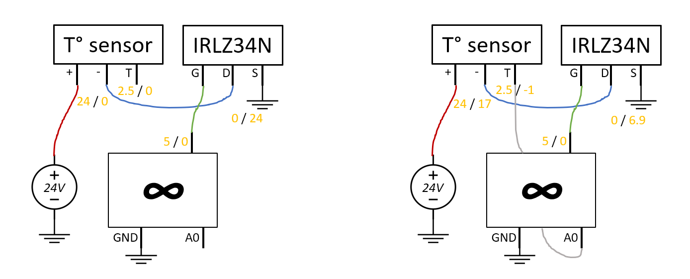
You can see below on the left the setup when the analog read is not connected; the yellow figures are the voltage readings: when the output pin is set to 5V, the transistor is conducting which loads the sensor with the supply voltage and allows the reading to be made (here, ~2.5V which is the room temperature of 25°C). When the pin is at 0, the transistor is blocking and the 24V power supply is found as V_DS. So far so good...
When I connect the A0 pin however, it all goes to shit as can be seen on the right figure. I've no notion of what is happening, the transistor is not blocking anymore and the sensor is partially powered... What is going wrong here ?
Thank you for all the answers ! I guess I should go & buy some P-channel mosfets to try this out then...
@LarryD I'm not sure about why a BJT is necessary in front of the Arduino; could you clarify this ? What is this circuit doing in the first place exactly ?
Thanks again for all the suggestions; as you can probably tell I am not very literate when it comes to electronics, so I have two additionnal questions:
As an alternative, would using relays work ? I'm already using one to pilot a 220V powered appliance; it looks like total overkill for a 24V sensor, but given that this voltage is problematic for high-side mosfet configurations, it would minimize the "hassle" (and satisfy my cowardly laziness).
I'm not sure I understand how the chips you showed are different from two mosfets in a common packaging. Which means i would not know how to use them. Do you know of any arduino tutorials using those ? I'm not even sure what they are generally called as an element, so my searches are not yielding anything relevant.