I am hoping to use an Arduino (probably MEGA) to read a few thermocouples for a senior design project. To make things easier, I was planning to use signals conditioners to take the thermocouple reading and scale it to a 4-20 mA linear signal. I was planning on running each signal through a 250ohm resistor, which would give me 1-5V across the resistor. I was hoping to use this voltage as my analogRead() signal. I haven't found anything that says I can't do that, however I want some confirmation before I carry on. If anyone has any insight I would appreciate it, and please let me know if anymore information would be helpful. Thanks!!
I am hoping to use an Arduino (probably MEGA) to read a few thermocouples for a senior design project. To make things easier, I was planning to use signals conditioners to take the thermocouple reading and scale it to a 4-20 mA linear signal. I was planning on running each signal through a 250ohm resistor, which would give me 1-5V across the resistor. I was hoping to use this voltage as my analogRead() signal. I haven't found anything that says I can't do that, however I want some confirmation before I carry on. If anyone has any insight I would appreciate it, and please let me know if anymore information would be helpful. Thanks!!
Yes, that is an acceptable and common way to read active 'loop powered' 4-20ma current loops. Be sure the 250 ohm resistor is an accurate one and that it's a ground based loop and that there is a common ground wire from the a arduino ground pin and the negitive terminal of the 'loop power supply' The biggest risk is if you ever accidently diconnect either lead of the resistor, full loop supply voltage will be presented to the analog input pin, which in many cases is 24vdc for common current loops and will damage the arduino chip.
If you've never done this before, best to draw out your proposed wiring design and post a link of the signal conditioner and we can see if there are any traps or faults in your proposed set-up.
Excellent, thank you for the help! This was one of the last pieces I needed before starting on the full design. I will certainly post a schematic once I have one.
I am hoping to use an Arduino (probably MEGA) to read a few thermocouples for a senior design project. To make things easier, I was planning to use signals conditioners to take the thermocouple reading and scale it to a 4-20 mA linear signal. I was planning on running each signal through a 250ohm resistor, which would give me 1-5V across the resistor. I was hoping to use this voltage as my analogRead() signal. I haven't found anything that says I can't do that, however I want some confirmation before I carry on. If anyone has any insight I would appreciate it, and please let me know if anymore information would be helpful. Thanks!!
Yes, that is an acceptable and common way to read active 'loop powered' 4-20ma current loops. Be sure the 250 ohm resistor is an accurate one and that it's a ground based loop and that there is a common ground wire from the a arduino ground pin and the negitive terminal of the 'loop power supply' The biggest risk is if you ever accidently diconnect either lead of the resistor, full loop supply voltage will be presented to the analog input pin, which in many cases is 24vdc for common current loops and will damage the arduino chip.
If you've never done this before, best to draw out your proposed wiring design and post a link of the signal conditioner and we can see if there are any traps or faults in your proposed set-up.
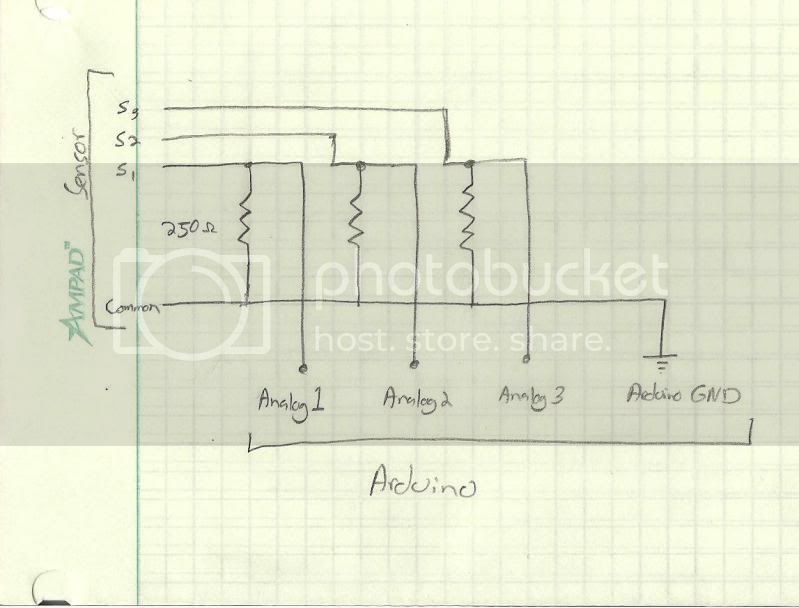
Here is the proposed circuit design. Hopefully that makes sense. I can put it in Multisim if that is helpful.
That's three sensors over three resistors.
That looks fine. The common of course will have to wire to each of the four COM terminals on the three devices, and each measurement wire, S1, S2, and S3 will wire to a "Iout" terminal on the devices.
At the refinery I worked at before retirement we used quite a few products like this from Omega, they always seemed to work OK. Most of their electronic modules are rebranded products actually made by others, but they always seemed to work to specifications and were better values then most of the mainstream process control industry supplies like Honeywell, Rosemount, etc.
I look forward to answering any additional questions in your own thread with details as outlined in the 'How to use this forum' thread on the top of the first page.