As already informed. PWM pins 44, 45 and 46 of the Mega 2560. No resistors.
I have used this same RGB LED configuration in other applications without problems. My range of PWM values are about 0~ 20% duty. Altought the problem is not related with duty cycle.
Have you added resistors yet?
I will suggest trying it on just the Mega board alone without any external circuitry. This will tell you whether the issue is related to the LED circuits or whether it's from the code. If your program doesn't have something already, you'll need to add some sort of output (e.g., blinking the built-in LED) to indicate the program startup so you'll know whether or not the reset is still occurring. If you do modify your code, make sure to verify that the issue still happens with the LEDs still attached to make sure you don't get inaccurate results from your experiment due to a "heisenbug".
Is it a genuine Mega, or a clone?
I already have tested this same Mega board and the led soldered with a simpler code and it runs normally not reseting....
Then maybe you made a wiring error...
You can't do "divide and conquer" troubleshooting by changing multiple things at once. It has to be one at a time. So either
The soldered board with your new code
or
The prototype with the "simpler" code.
Otherwise it could still be either cause...
Because, it is crucial to understand whether it is a code or hardware problem, in order to get closer to a solution.
It is MEGA 2560 PRO (EMBED) from robotdyn.com
https://robotdyn.com/mega-2560-pro-embed-ch340g-atmega2560-16au.html
Okay, there should be no problems with that board. Did we ever get a wiring diagram or prototype photos from you? See reply #20 for example...
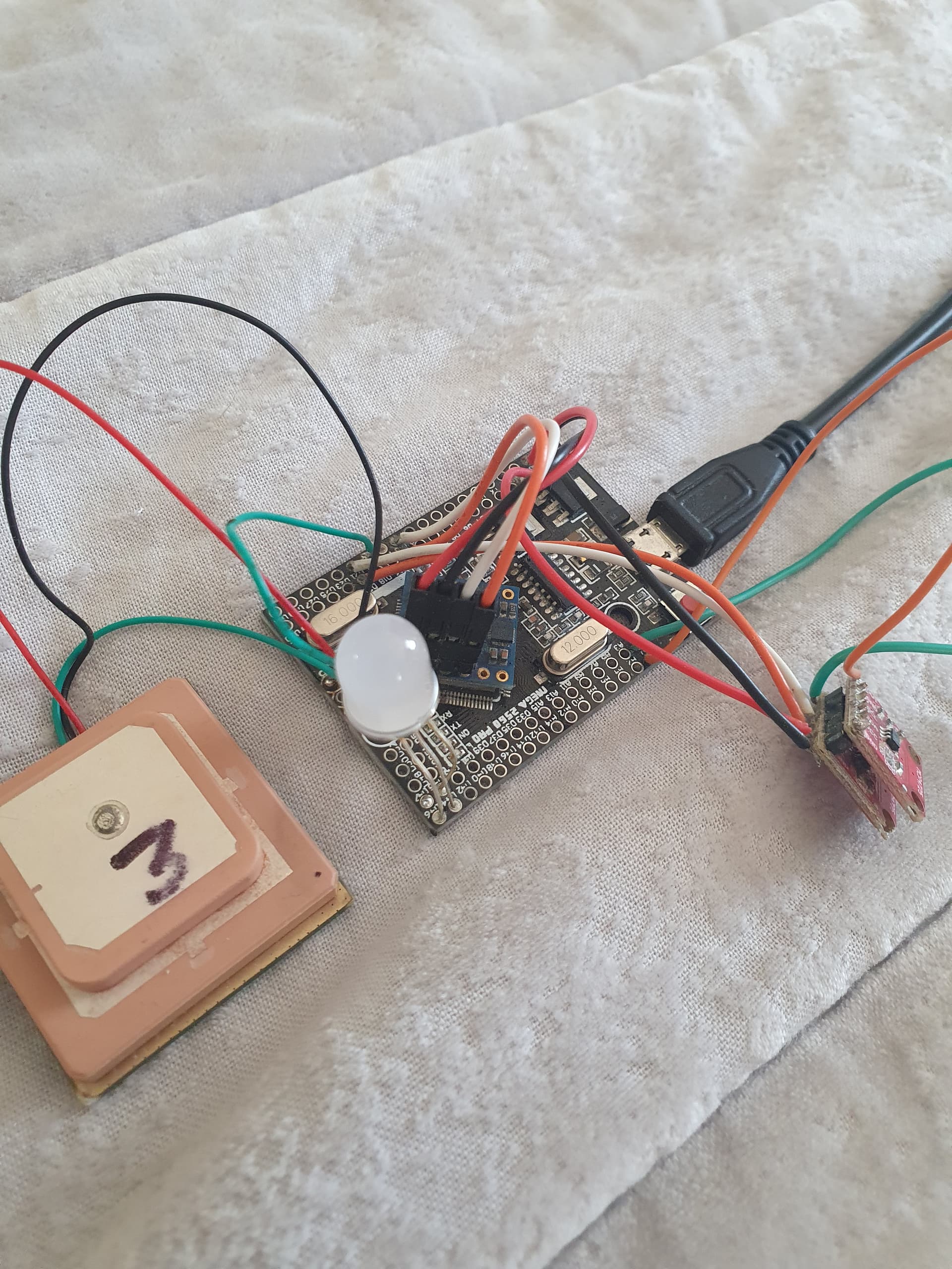
Thanks, that is a good start. However, there are some fairly unusual parts and mystery hardware on there. The LED connections are invisible. A diagram would help us sort it out. I'm sure you would understand, without information we can only guess...
The HW parts are described in the code. There are a GPS module only sending serial 115200 baud , an AHRS GY953 (compass) controled by TX and RX serial 9600 baud, and two MCP4725 DACs... controlled by SCL SDA and the RGB LED common anode
I've explained to you that descriptions alone, aren't enough. Good luck.
Let’s answer reply #20 first…
Hmm ... no current limiting resistors. Now there's up to 3 overloaded outputs. With all 3 outputs all on the same port "L", now we have an overloaded port ... yikes!
Try adding series resistors to your led pins ... anything from 270R to 1K, then see if the problem goes away.
I've already tested this hypothesis. It's not an overload problem because the same board loaded with a simple program works correctly. Another contradiction is that the problem only appears when only 1 led is activated. By setting 2 or 3 LEDs at same time, the problem should get worse but that's not what happens...
How about testing the resistor hypothesis by adding them. Just to get it out of the way... it's easy and definitive.
This topic was automatically closed 120 days after the last reply. New replies are no longer allowed.