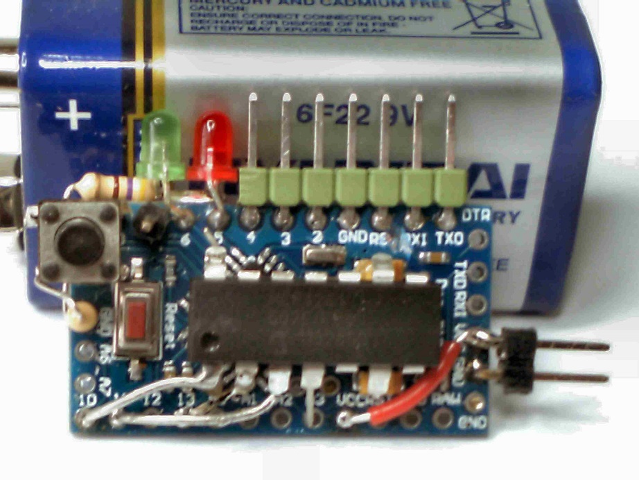
@all, i am trying to hack a R/C car with a L293 controlling the back motor and a servo for steering.
I am going to use BT commander to control it. My code is attached.
android_bluetooth_robot.ino (9.63 KB)
@all, i am trying to hack a R/C car with a L293 controlling the back motor and a servo for steering.
I am going to use BT commander to control it. My code is attached.
android_bluetooth_robot.ino (9.63 KB)
Hi Woody
I know very little about Android phones and WiFi ... so I've a question for you regarding the total rc commander version of your App
This is the dataflow diagram for Total BT Commander, as implemented for this RC tank demo
Bluetooth:
Two way communication with the BT card, strickly identical to Joystick BT Commander
WiFi:
The video stream from the IP camera is sent to the home router, then to your Android device
This may not be convenient for outdoor activities ![]()
For this reason, the tank has an onboard mini router
A smartphone can also be used as an IP camera
WiFi tethering option allow direct connection with Total RC Commander, without any router
Now, to start connection from Total BT Commander, go to Options/Video properties/Camera feed URL
You should enter
For Wanscam IP cam: "http://192.168.1.10:99/videostream.cgi?user=admin1&pwd=&resolution=32&rate=0"
For the Moto G smartphone: "http://192.168.1.12:8080/videofeed"
To get Total RC Commander, look here
Do you think that this product would be compatible with your App as it would make a neat remote camera for the wheelchair users that use my interface?
http://www.aliexpress.com/store/product/Mini-WiFi-Car-Rearview-Camera-Wireless-Back-Up-Reserve-170-Degree-Waterproof-Cam-Support-Android-System/138455_1727304917.html
This nice device is an IP camera with built-in router
It should work with Total BT Commander ** EDIT: it doesn't so far **
@Antonio
Please confirm App version and BT card baud rate
Keep-It-Stupid-Simple, forget steppers for the moment.
Can you see the Joystick data on the Arduino Serial Monitor using plain V2.0 sketch
Follow Woody's advices
This nice device is an IP camera with built-in router
It should work with Total BT Commander
So ...suck it and see ![]()
Hi Kas and Woody,
This is the code that I'm uploading to the arduino, that is the right one right?
As far as when I'm using the Joystick BT Commander goes, when I bring up the serial port, all I see is,
AndroTest V2.0 - @kas2014
demo for V5. x App
Down at the bottom I see,
Check mark on Autoscroll Both NL & CR is selected - 57600 baud is selected.
When I'm actually moving the joystick around, I see nothing else on the serial port. How do I know that the Joystick BT Commander is communicating with the Arduino?
Thanks......Antonio
#define VERSION     "\n\nAndroTest V2.0 - @kas2014\ndemo for V5.x App"

// V2.0  changed to pure ASCII Communication Protocol ** not backward compatible **
// V1.4  improved communication errors handling
// V1.3  renamed for publishing, posted on 09/05/2014
// V1.2  Text display   ** not backward compatible **
// V1.1  Integer display
// V1.0  6 buttons + 4 data char implemented

// Demo setup:
// Button #1 controls pin #13 LED
// Button #4 toggle datafield display rate
// Button #5 configured as "push" button (momentary)
// Other buttons display demo message

// Arduino pin#2 to TX BlueTooth module
// Arduino pin#3 to RX BlueTooth module
// make sure your BT board is set @57600 bps
// better remove SoftSerial for PWM based projects

// For Mega 2560:
// remove   #include "SoftwareSerial.h", SoftwareSerial mySerial(2,3);
// search/replace  mySerial  >> Serial1
// pin#18 to RX bluetooth module, pin#19 to TX bluetooth module

#include "SoftwareSerial.h"

#define    STX          0x02
#define    ETX          0x03
#define    ledPin       13
#define    SLOW         750                            // Datafields refresh rate (ms)
#define    FAST         250                             // Datafields refresh rate (ms)

SoftwareSerial mySerial(2,3);                           // BlueTooth module: pin#2=TX pin#3=RX
byte cmd[8] = {0, 0, 0, 0, 0, 0, 0, 0};                 // bytes received
byte buttonStatus = 0;                                  // first Byte sent to Android device
long previousMillis = 0;                                // will store last time Buttons status was updated
long sendInterval = SLOW;                               // interval between Buttons status transmission (milliseconds)
String displayStatus = "xxxx";                          // message to Android device

void setup()  {
 Serial.begin(57600);
 mySerial.begin(57600);                                // 57600 = max value for softserial
 pinMode(ledPin, OUTPUT);
 Serial.println(VERSION);
 while(mySerial.available())  mySerial.read();         // empty RX buffer
}

void loop() {
 if(mySerial.available())  {                           // data received from smartphone
   delay(2);
   cmd[0] =  mySerial.read();
   if(cmd[0] == STX)  {
     int i=1;
     while(mySerial.available())  {
       delay(1);
       cmd[i] = mySerial.read();
       if(cmd[i]>127 || i>7)                 break;     // Communication error
       if((cmd[i]==ETX) && (i==2 || i==7))   break;     // Button or Joystick data
       i++;
     }
     if     (i==2)          getButtonState(cmd[1]);    // 3 Bytes  ex: < STX "C" ETX >
     else if(i==7)          getJoystickState(cmd);     // 6 Bytes  ex: < STX "200" "180" ETX >
   }
 }
 sendBlueToothData();
}

void sendBlueToothData()  {
 static long previousMillis = 0;
 long currentMillis = millis();
 if(currentMillis - previousMillis > sendInterval) {   // send data back to smartphone
   previousMillis = currentMillis;

// Data frame transmitted back from Arduino to Android device:
// < 0X02   Buttons state   0X01   DataField#1   0x04   DataField#2   0x05   DataField#3    0x03 >
// < 0X02      "01011"      0X01     "120.00"    0x04     "-4500"     0x05  "Motor enabled" 0x03 >    // example

   mySerial.print((char)STX);                                             // Start of Transmission
   mySerial.print(getButtonStatusString());  mySerial.print((char)0x1);   // buttons status feedback
   mySerial.print(GetdataInt1());            mySerial.print((char)0x4);   // datafield #1
   mySerial.print(GetdataFloat2());          mySerial.print((char)0x5);   // datafield #2
   mySerial.print(displayStatus);                                         // datafield #3
   mySerial.print((char)ETX);                                             // End of Transmission
 }
}

String getButtonStatusString()  {
 String bStatus = "";
 for(int i=0; i<6; i++)  {
   if(buttonStatus & (B100000 >>i))      bStatus += "1";
   else                                  bStatus += "0";
 }
 return bStatus;
}

int GetdataInt1()  {              // Data dummy values sent to Android device for demo purpose
 static int i= -30;              // Replace with your own code
 i ++;
 if(i >0)    i = -30;
 return i;
}

float GetdataFloat2()  {           // Data dummy values sent to Android device for demo purpose
 static float i=50;               // Replace with your own code
 i-=.5;
 if(i <-50)    i = 50;
 return i;
}

void getJoystickState(byte data[8])    {
 int joyX = (data[1]-48)*100 + (data[2]-48)*10 + (data[3]-48);       // obtain the Int from the ASCII representation
 int joyY = (data[4]-48)*100 + (data[5]-48)*10 + (data[6]-48);
 joyX = joyX - 200;                                                  // Offset to avoid
 joyY = joyY - 200;                                                  // transmitting negative numbers

 if(joyX<-100 || joyX>100 || joyY<-100 || joyY>100)     return;      // commmunication error

// Your code here ...
   Serial.print("Joystick position:  ");
   Serial.print(joyX);
   Serial.print(", ");
   Serial.println(joyY);
}

void getButtonState(int bStatus)  {
 switch (bStatus) {
// -----------------  BUTTON #1  -----------------------
   case 'A':
     buttonStatus |= B000001;        // ON
     Serial.println("\n** Button_1: ON **");
     // your code...
     displayStatus = "LED <ON>";
     Serial.println(displayStatus);
     digitalWrite(ledPin, HIGH);
     break;
   case 'B':
     buttonStatus &= B111110;        // OFF
     Serial.println("\n** Button_1: OFF **");
     // your code...
     displayStatus = "LED <OFF>";
     Serial.println(displayStatus);
     digitalWrite(ledPin, LOW);
     break;

// -----------------  BUTTON #2  -----------------------
   case 'C':
     buttonStatus |= B000010;        // ON
     Serial.println("\n** Button_2: ON **");
     // your code...
     displayStatus = "Button2 <ON>";
     Serial.println(displayStatus);
     break;
   case 'D':
     buttonStatus &= B111101;        // OFF
     Serial.println("\n** Button_2: OFF **");
     // your code...
     displayStatus = "Button2 <OFF>";
     Serial.println(displayStatus);
     break;

// -----------------  BUTTON #3  -----------------------
   case 'E':
     buttonStatus |= B000100;        // ON
     Serial.println("\n** Button_3: ON **");
     // your code...
     displayStatus = "Motor #1 enabled"; // Demo text message
     Serial.println(displayStatus);
     break;
   case 'F':
     buttonStatus &= B111011;      // OFF
     Serial.println("\n** Button_3: OFF **");
     // your code...
     displayStatus = "Motor #1 stopped";
     Serial.println(displayStatus);
     break;

// -----------------  BUTTON #4  -----------------------
   case 'G':
     buttonStatus |= B001000;       // ON
     Serial.println("\n** Button_4: ON **");
     // your code...
     displayStatus = "Datafield update <FAST>";
     Serial.println(displayStatus);
     sendInterval = FAST;
     break;
   case 'H':
     buttonStatus &= B110111;    // OFF
     Serial.println("\n** Button_4: OFF **");
     // your code...
     displayStatus = "Datafield update <SLOW>";
     Serial.println(displayStatus);
     sendInterval = SLOW;
    break;

// -----------------  BUTTON #5  -----------------------
   case 'I':           // configured as momentary button
//      buttonStatus |= B010000;        // ON
     Serial.println("\n** Button_5: ++ pushed ++ **");
     // your code...
     displayStatus = "Button5: <pushed>";
     break;
//   case 'J':
//     buttonStatus &= B101111;        // OFF
//     // your code...
//     break;

// -----------------  BUTTON #6  -----------------------
   case 'K':
     buttonStatus |= B100000;        // ON
     Serial.println("\n** Button_6: ON **");
     // your code...
      displayStatus = "Button6 <ON>"; // Demo text message
    break;
   case 'L':
     buttonStatus &= B011111;        // OFF
     Serial.println("\n** Button_6: OFF **");
     // your code...
     displayStatus = "Button6 <OFF>";
     break;
 }
// ---------------------------------------------------------------
}
Antonio,
Again: Please confirm App version and BT card baud rate
Based on your information, your RX/TX wires are probably inverted, try reversing D2 and D3
EDIT: Looking again at your video, I can see the datafields are updated according to V2 sketch code
The Arduino >> Android communication is OK
Try changing mySerial.begin(57600) to mySerial.begin(9600) or mySerial.begin(19200)
EDIT2:
This is the code that I'm uploading to the arduino, that is the right one right?
Yes, assuming you didn't modify it
How do I know that the Joystick BT Commander is communicating with the Arduino?
Blinking TX led shows incoming data from Android (as labeled on my board, with Serial Monitor enabled)
Carefully check your D2 connection (white cable)
Also disconnect all motor driver cables, just pure V2 code, to avoid possible interaction with Softserial
Let us have a new video, showing the new set up, including BT card and PC screen
We WILL make it out ![]()
I send you Total BT Commander V5.2, please check your mail
First, check the Bluetooth side, should work exactly as Joystick BT Commander
Let me have your IP camera model
I have tried to combine your stepper prog with Kas's AndroTest V2.0... ONCE the AndroTest program and serial comms is sorted... then I'll post it for you and you can try it out.
@ Kas
APK received .... I'll need to purchase the back up camera first before I can play.
EDIT: Looking again at your video, I can see the datafields are updated according to V2 sketch code
The Arduino >> Android communication is OK
Isn't that proof of the myserial Blue Tooth baud rate being correct.... or am I once again missing something?
Isn't that proof of the myserial Blue Tooth baud rate being correct.... or am I once again missing something?
You are perfectly right :-[
I edited my message
Kas,
The originator of the request for a simple camera feed for his chair went ahead and bought the camera system...he emailed me this evening.
Woody I got the WiFi back up camera working on my phone using CarMoniter.apk. It works really nice. This is the camera I got: http://www.dx.com/p/w-one-ip66-wireless-wi-fi-300kp-car-rearview-camera-system-for-andriod-black-310074#.VIzMtcYkCnA
I got it off ebay though from a different seller and cheaper.
Could you get me the Total BT Commander apk so I could test it?
Thanks,
Pat Tallino
Beach Mobility Inc.
So I passed on the RC Commander App ( I owe you 2 more Euro's ) .
His reply came back an hour later...
Thanks, but no luck. The CarMoniter app automatically finds the video signal when the phone is connected to the cameras WiFi router.
Total Rc Commander seems to need an ip address and port but I have no way of knowing that.
CarMoniter app download link below.
http://www.sendspace.com/file/rbifoo
Woody
Thanks, but no luck. The CarMoniter app automatically finds the video signal when the phone is connected to the cameras WiFi router.
Total Rc Commander seems to need an ip address and port but I have no way of knowing that.
Please confirm that nothing was entered in CarMoniter (user, password...), to obtain a video connection
Thanks Kas and Woody,
I'll be posting a new video later today, showing the sequence of events to make sure that isn't my problem.
I appreciate your help............Thanks..........Antonio
kas:
Please confirm that nothing was entered in CarMoniter (user, password...), to obtain a video connection
Kas ..here's a transcript of the conversion.
Hi Pat,
I've also been asked to confirm that once the Wifi connection has been setup on the phone ...all you do is start the App and bingo a video appears?.
I assume that the Car monitor's WiFi shows up on the Android phone under Settings -WiFi- with the name GLW-CAR-R and simply requires a password to connect ?
Note that we are asking questions blind and making assumptions ...so feel free to say "no no" that's not how it works.... AND STEP ME THRU THE PROCESS.
Any chance of a scan of the relevant page from the manual?
Woody
Yes thats correct. If you start the app before you connect to WiFi, you have an option to choose "Normal" or "High" video quality. But if the phone, Samsung Galaxy Note 4 in my case, is already connected to the WiFi, which is GLW-CAR-R0000795, then when you open the CarMoniter App, the video just starts automatically full screen like a backup moniter. There are no options within the app for any setup
Hope this helps.
Woody
EDIT :- This seems to be the installation manual for the same backup camera but for a different supplier.
AntonioLopez:
Thanks Kas and Woody,I'll be posting a new video later today, showing the sequence of events to make sure that isn't my problem.
I appreciate your help............Thanks..........Antonio
The communication TO the Android phone ( TX of Arduino to RX of Blue Tooth ) seems fine.
The problem appears to be one of Blue Tooth communication FROM the Android phone to the Arduino ( TX of Blue Tooth to RX of Arduino ).
This could just be a bad connection or wire as indicated by Kas ... or it's remotely possible that it is the UNO's pin... or a damaged Blue Tooth module.
AntonioLopez:
Thanks Kas and Woody,I'll be posting a new video later today, showing the sequence of events to make sure that isn't my problem.
I appreciate your help............Thanks..........Antonio
Here's a screen shot of the pot outputs after I've integrated the stepper App into the BT Commander.
The first column after the PotValA & B swing from 0 - 2047 with 1023 as the center using the BT Joystick as an input.
Hi Woody, and Kass,
Wow, great work Woddy, that screen shot is amazing and proof that everything I'm doing is doing absolutely nothing.
Here's another short video showing you my sequence of events.
I don't want to take up any more of your and Kass's time, so at this point, how do you feel about fixing this problem and I can pay you through Paypal, hopefully this isn't frowned upon on this site.
I'm pretty burned out, this is the second bluetooth module that I've tried, and I've been to what seems a thousand - how to sites, so I don't know what to say, except that I want to move forward.
Here's the code that I've been using with the potentiometer and the small stepper.
/*------------------------------------------------------
StepperPot_11
Arduining.com 13 APRIL 2013

A stepper motor follows a potentiometer on analog input 5.
A software low-pass filter is used to reduce the noise in the analog reading.
After 3 seconds of inactivity the motor coils are turned OFF to save energy.
The RED_LED is used to signal when the stepper is powered.

Hardware:
LaunchPad with MSP430G2553.
Driver: ULN2003A
Stepper Motor:  28BYJ48, 5VDC, step pangle 5.625 °
                Gear reduction 64:1
                No-load starting frequency:> = 500PPS (4 rpm)
                Coil resistance 60 Ohms.
 -----------------------------------------------------*/

#include <Stepper.h>

// change this to the number of steps on your motor
#define  STEPSREV    2047    // 64(fullsteps) * 64 (reduction ratio)
#define  COIL1       11
#define  COIL2       9
#define  COIL3       10
#define  COIL4       8
#define  POT         0
#define  ENER        13
#define  TIMEOUT     3000    //Turns off after 3 secs of inactivity.

// create an instance of the stepper class, specifying
// the number of steps per revolution and pins atached to motor coils.
Stepper myStepper(STEPSREV, COIL1, COIL2, COIL3, COIL4);
int PotVal;
int LastPotVal= 0 ;          // To implement a software Low-Pass-Filter
int pos = 0;              // stepper position(0-4096)->(0-360°)
unsigned long stamp = 0;  // last move time stamped.

void setup()
{
  myStepper.setSpeed(4);  // set the motor speed to 4 RPM
  pinMode(ENER, OUTPUT);  // status led (coils energized).
//  Serial.begin(9600);   //for debuging.
}

void loop(){

  PotVal = analogRead(POT);       // Potentiometer value range 0-1023

  PotVal= map(PotVal,0,1023,0,2047);      // Map pot range in the stepper range.
  PotVal= PotVal * 0.1 + LastPotVal * 0.9 ;  // Filtering to reduce noise.
  LastPotVal= PotVal;

//  Serial.print(Val);              // For debuging.
//  Serial.print("   ");            //    "
//  Serial.println(pos);            //    "
//  delay(500);                     //    "

  if(abs(PotVal - pos)> 4){              //if diference is greater than 4 steps.
      if((PotVal - pos)> 0){
          digitalWrite(ENER, HIGH);   //Motor energized.
          myStepper.step(1);           // move one step to the right.
          pos++;
          }
      if((PotVal - pos)< 0){
          digitalWrite(ENER, HIGH);   //Motor energized.
          myStepper.step(-1);            // move one step to the left.
          pos--;
          }
      stamp = millis();               // stamp actual time.
      }
  else {
      if((millis() - stamp) > TIMEOUT){   //Turn Off coils after TIMEOUT.
          digitalWrite(COIL1, LOW);
          digitalWrite(COIL2, LOW);
          digitalWrite(COIL3, LOW);
          digitalWrite(COIL4, LOW);
          digitalWrite(ENER, LOW);    //Motor de-energized.
          }
      }

}
Thanks to the both of you again............Antonio
Antonio,
For the moment
Android >> Arduino not OK
Arduino >> Android OK
Joystick BT Commander V4.x would create this exact situation
Just to make sure, uninstall the App and reload from Google Play
I don't want to take up any more of your and Kass's time, so at this point, how do you feel about fixing this problem and I can pay you through Paypal, hopefully this isn't frowned upon on this site.
I'm pretty burned out, this is the second bluetooth module that I've tried, and I've been to what seems a thousand - how to sites, so I don't know what to say, except that I want to move forward.
I could easily program a pro mini and post it to you... BUT ..the fix is likely to be simple if you persevere with the guidance being provided.
Follow Kas's advice ...uninstall BT Commander from your phone & download the latest version of the App
If your interested in knowing what version of Kas's software your currently running go to the screen line that pops up at the bottom of the App with Connect Options reset Opt About and press About.
Mine says Joystick BT Commander V5.2
Hi Guys, and once again thanks for your help.
I reinstalled Commander to make sure and I do have V5.2 installed, problem is the same.
Later on today I'll setup the HC5 to see what happens, I didn't want to setup a voltage divider, that's why I bought an HC6.
Woody, what do you mean, program a pro mini?
Thanks...........Antonio