Voltage is measured between 2 points. If you were using your meter to measure the voltage at your wall socket, you would put one probe in the "HOT" hole, where would you put the other probe? Sticking it up in the air is NOT the right answer.
It will work with either live or neutral, you don't need both
This is what i was looking. What components are used here?
First you need to know the maximum current in the wire.
Wire is comming from a switch. So it will not have a load
Jim,
I don't see how that is possible. To detect voltage you need 2 connections. Even the tester @arpa123 showed in post #14 has 2 connections: the screwdriver tip and the user's finger.
And, to be clear even my suggestion has 2 connections, the other one being earth via the low voltage part of the circuit. It's such high impedance it probably (hopefully) works even if not connected to earth.
1 Like
If no load then there will be no current flow, so there is no way to tell if wire is cut or not.
It has two connections. See the two screws.
Have I misread somewhere? I didn't think the wire was cut. Perhaps I missed something.
I saw, but you said:
Which is one wire.
@arpa123 ,
I think there is confusion here about what you are trying to do, I certainly feel confused. Before I continue please clarify what you want to do.
Also, I'm not clear if you have rejected my idea and don't want to use it, or if you are not sure if it will work for you and want to know more before deciding. Please clarify.
Appears the OP wants to measure the voltage at the load side of a switch without a connection to neutral or earth ground.
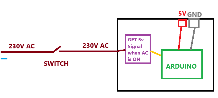
i just want to check if switch is on or off (it has 220v AC line)
what i need is a solution for the PURPLE color square in image
No the result of that word salad will be BANG.
You, well not you because you don't have the knowledge, can implement @PerryBebbington method on a PCB if you know about creepage and clearance regulations.
See
Get a small demon and record if it says "ouch" or is silent.
The use of demons is widely discuses in the books by Terry Pratchett. They can be used to paint as well, although they complain at the frame rate when used as a Surveillance camera.
1 Like
Then my suggestion will not work.
First thing I learned about electrical things 65 years ago (NOT static electricity):
"Electric current flows in a loop called a circuit from one voltage point to another point with a different voltage".
1 Like
The method I have used several times in the distant past was the simple optical sensor method that's already been mentioned.
In my case (probably before opto-isolaters existed, or I could afford them) was to glue a neon indicator light inside a discarded black plastic pen tube. And facing it, a photo resistor. An equally basic circuit (resistor, transistor, DC voltage supply) gave me the low voltage I needed for the rest of the circuit.
Obviously both sides needed grounding.
If I needed the circuit you require today, I'd use the basic wall adapter suggested by Tom in post #2.
2 Likes
Is the PCB ground connected to earth ground? If not, there will be NO current flow, thus, NO voltage difference, understand?
Don't forget to add a 1M series resistor in line with the neon. As a neon once struck has very little resistance and so would blow up.
1 Like
I decided not to include an example for @arpa123 . But for you and others who remember CMOS and the like...
And 20 years later I discovered Arduino!
Wish I still did such a decent job with my documentation!
![]()

1 Like
All you need is a USB power cube and an old USB cable. Cut one end off the USB cable and the red and black wire will give you 5V/GND when the power is on and 0V when power is off. Maybe throw a 10K resistor on the 5V line to limit current, but if you go direct to a digital input, the internal circuitry should be enough.
1 Like
See post #2
Tom.. ![]()
![]()
![]()
![]()