Hello,
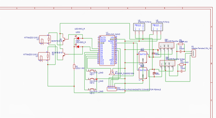
I'm working on an ATS with two sources: Main and Gen, using a Nano board. I have created the code as shown below, but I'm facing an issue with the priority between Main and Gen. Specifically, when Main goes offline, the ATS should switch to Gen after a delay of 5 seconds. However, when Main is offline and Gen is running, the ATS switches back to Main after a delay. I have tried to identify the issue in the code but couldn't find the problem. I would like to update the code to meet this condition. |
| Condition | Action |
|---|---|
| Main HIGH, Gen High |
Main HIGH, Gen OFF|Wait MainDelay → switch to Main
Wait MainDelay → switch to Main|
|Main LOW, Gen HIGH|Wait GenDelay → switch to Generator, no switch to main if its LOW|
|Gen ON, Main returns|Immediately OFF Gen → Wait MainDelay → switch to Main|
I’m writing to seek your support and advice. and thanks to anyone help me.
Thanks
Norman
code :
#include <LiquidCrystal_I2C.h>
#include <EEPROM.h>
LiquidCrystal_I2C lcd(0x27, 16, 2);
// Pin Definitions
const int mainPin = 2;
const int genPin = 3;
const int mainRelay = 4;
const int genRelay = 5;
const int setButton = 6;
const int upButton = 7;
const int downButton = 8;
const int buzzer = 9;
// EEPROM addresses
const int addrMainDelay = 0;
const int addrGenDelay = 1;
const int addrBuzzerEnable = 2;
const int addrMainTone = 3;
const int addrGenTone = 5;
const int addrToneDuration = 7;
// Settings Variables
int mainDelay = 5;
int genDelay = 5;
bool buzzerEnabled = true;
int mainTone = 1000;
int genTone = 2000;
int toneDuration = 200;
// UI and Timing
int menuIndex = 0;
bool inSettings = false;
bool saveSettings = false;
unsigned long buttonPressTime = 0;
bool longPressDetected = false;
unsigned long previousMillis = 0;
const long interval = 500;
// Icons
byte iconPower[8] = {B00100, B01110, B11111, B10101, B11111, B01110, B00100, B00000};
byte iconGear[8] = {B00000, B10101, B01110, B11111, B01110, B10101, B00000, B00000};
// Setup
void setup() {
pinMode(mainPin, INPUT);
pinMode(genPin, INPUT);
pinMode(mainRelay, OUTPUT);
pinMode(genRelay, OUTPUT);
pinMode(setButton, INPUT_PULLUP);
pinMode(upButton, INPUT_PULLUP);
pinMode(downButton, INPUT_PULLUP);
pinMode(buzzer, OUTPUT);
lcd.init();
lcd.backlight();
lcd.createChar(1, iconPower);
lcd.createChar(2, iconGear);
loadSettings();
tone(buzzer, 1500, 150); delay(200);
tone(buzzer, 2000, 150); delay(200);
tone(buzzer, 2500, 150); delay(500);
lcd.setCursor(0, 0);
lcd.print(" ATS Controller ");
lcd.setCursor(0, 1);
lcd.print("Initializing...");
delay(2000);
}
// Main Loop
void loop() {
unsigned long currentMillis = millis();
// Button Long Press to Enter/Exit Settings
if (digitalRead(setButton) == LOW && !longPressDetected) {
if (buttonPressTime == 0) buttonPressTime = currentMillis;
if (currentMillis - buttonPressTime > 1000) {
inSettings = !inSettings;
menuIndex = 0;
longPressDetected = true;
}
} else if (digitalRead(setButton) == HIGH) {
buttonPressTime = 0;
longPressDetected = false;
}
if (inSettings) {
handleSettings();
} else {
handlePowerLogic();
if (currentMillis - previousMillis >= interval) {
previousMillis = currentMillis;
showStatus();
}
}
}
// Handle Power Logic
void handlePowerLogic() {
bool m = digitalRead(mainPin) == HIGH;
bool g = digitalRead(genPin) == HIGH;
bool mainActive = digitalRead(mainRelay);
bool genActive = digitalRead(genRelay);
if (m && g) {
if (genActive) {
digitalWrite(genRelay, LOW); // Turn off Gen
showCountdownBar("Main", mainDelay);
digitalWrite(mainRelay, HIGH);
beep(mainTone);
} else if (!mainActive) {
showCountdownBar("Main", mainDelay);
digitalWrite(mainRelay, HIGH);
beep(mainTone);
}
} else if (m && !g) {
if (!mainActive) {
showCountdownBar("Main", mainDelay);
digitalWrite(mainRelay, HIGH);
digitalWrite(genRelay, LOW);
beep(mainTone);
}
} else if (!m && g) {
if (!genActive) {
digitalWrite(mainRelay, LOW);
showCountdownBar("Gen", genDelay);
digitalWrite(genRelay, HIGH);
beep(genTone);
}
} else {
// No power available
digitalWrite(mainRelay, LOW);
digitalWrite(genRelay, LOW);
}
}
// Countdown Bar
void showCountdownBar(String label, int seconds) {
lcd.clear();
lcd.setCursor(0, 0);
lcd.print("Wait: " + label);
for (int i = 0; i <= seconds; i++) {
lcd.setCursor(0, 1);
int barLen = map(i, 0, seconds, 0, 16);
for (int j = 0; j < 16; j++) {
lcd.print(j < barLen ? char(255) : ' ');
}
delay(1000);
}
}
// Show Status
void showStatus() {
bool m = digitalRead(mainPin) == HIGH;
bool g = digitalRead(genPin) == HIGH;
bool mainActive = digitalRead(mainRelay);
bool genActive = digitalRead(genRelay);
lcd.setCursor(0, 0);
lcd.print("M:"); lcd.print(m ? "ON " : "OFF");
lcd.print(" G:"); lcd.print(g ? "ON" : "OFF");
lcd.setCursor(0, 1);
if (mainActive) {
lcd.write(1); lcd.print(" Main Active ");
} else if (genActive) {
lcd.write(2); lcd.print(" Gen Active ");
} else {
lcd.print("No Power ");
}
}
// Settings Menu
void handleSettings() {
lcd.clear();
switch (menuIndex) {
case 0: lcd.print("Main Delay: "); lcd.print(mainDelay); lcd.print("s"); break;
case 1: lcd.print("Gen Delay: "); lcd.print(genDelay); lcd.print("s"); break;
case 2: lcd.print("Buzzer: "); lcd.print(buzzerEnabled ? "ON " : "OFF"); break;
case 3: lcd.print("Main Tone: "); lcd.print(mainTone); break;
case 4: lcd.print("Gen Tone: "); lcd.print(genTone); break;
case 5: lcd.print("Buzz Dur: "); lcd.print(toneDuration); lcd.print("ms"); break;
case 6: lcd.print("Save & Exit"); break;
}
delay(200);
if (digitalRead(upButton) == LOW) {
switch (menuIndex) {
case 0: if (mainDelay < 60) mainDelay++; break;
case 1: if (genDelay < 60) genDelay++; break;
case 2: buzzerEnabled = !buzzerEnabled; break;
case 3: mainTone += 100; break;
case 4: genTone += 100; break;
case 5: if (toneDuration < 1000) toneDuration += 50; break;
}
} else if (digitalRead(downButton) == LOW) {
switch (menuIndex) {
case 0: if (mainDelay > 1) mainDelay--; break;
case 1: if (genDelay > 1) genDelay--; break;
case 2: buzzerEnabled = !buzzerEnabled; break;
case 3: if (mainTone > 100) mainTone -= 100; break;
case 4: if (genTone > 100) genTone -= 100; break;
case 5: if (toneDuration > 50) toneDuration -= 50; break;
}
} else if (digitalRead(setButton) == LOW && !longPressDetected) {
menuIndex++;
if (menuIndex > 6) menuIndex = 0;
if (menuIndex == 6) saveSettings = true;
}
if (saveSettings) {
saveSettings = false;
saveToEEPROM();
inSettings = false;
}
}
// Beep
void beep(int frequency) {
if (buzzerEnabled) {
tone(buzzer, frequency, toneDuration);
}
}
// EEPROM Load
void loadSettings() {
mainDelay = constrain(EEPROM.read(addrMainDelay), 1, 60);
genDelay = constrain(EEPROM.read(addrGenDelay), 1, 60);
buzzerEnabled = EEPROM.read(addrBuzzerEnable);
EEPROM.get(addrMainTone, mainTone);
EEPROM.get(addrGenTone, genTone);
EEPROM.get(addrToneDuration, toneDuration);
}
// EEPROM Save
void saveToEEPROM() {
EEPROM.write(addrMainDelay, mainDelay);
EEPROM.write(addrGenDelay, genDelay);
EEPROM.write(addrBuzzerEnable, buzzerEnabled);
EEPROM.put(addrMainTone, mainTone);
EEPROM.put(addrGenTone, genTone);
EEPROM.put(addrToneDuration, toneDuration);
}
