Hey guys, let me start off by telling everyone that I am new here. I've been playing with some simple circuits with an Arduino Mega off and on for a little over a year now not to mention my Prusa utilizes one as well. I'm not very good at programming yet but I'm getting better Anyway on to my issue.
I'm trying to read RPMs off the flywheel magnet of a Briggs and Stratton engine using a VR sensor. The problem is the magnet is really strong and I get some really high voltage readings (just turning engine over with the starter looks to be about 45 volts peak to peak) from the sensor and from what I can figure the voltage only increases as the RPMs increase. I need a circuit that can attenuate this signal and turn it into a square wave so my Arduino can read it but I'm not sure how to go about doing it. I'm pretty sure I'll need a Schmitt Trigger but I know it cant handle that kind of voltage. Any help is appreciated.
Firstly you would either divide down th voltage with a resistive divider, or perhaps clamp it
using a resistor-diode or resistor-zener divider. Yes schmitt-trigger inputs would probably
then be a good idea to get clean single transistions.
You may also be able to use an opto-isolater if enough current is available. Again a resistor
would be used to limit the current and tame the high voltages.
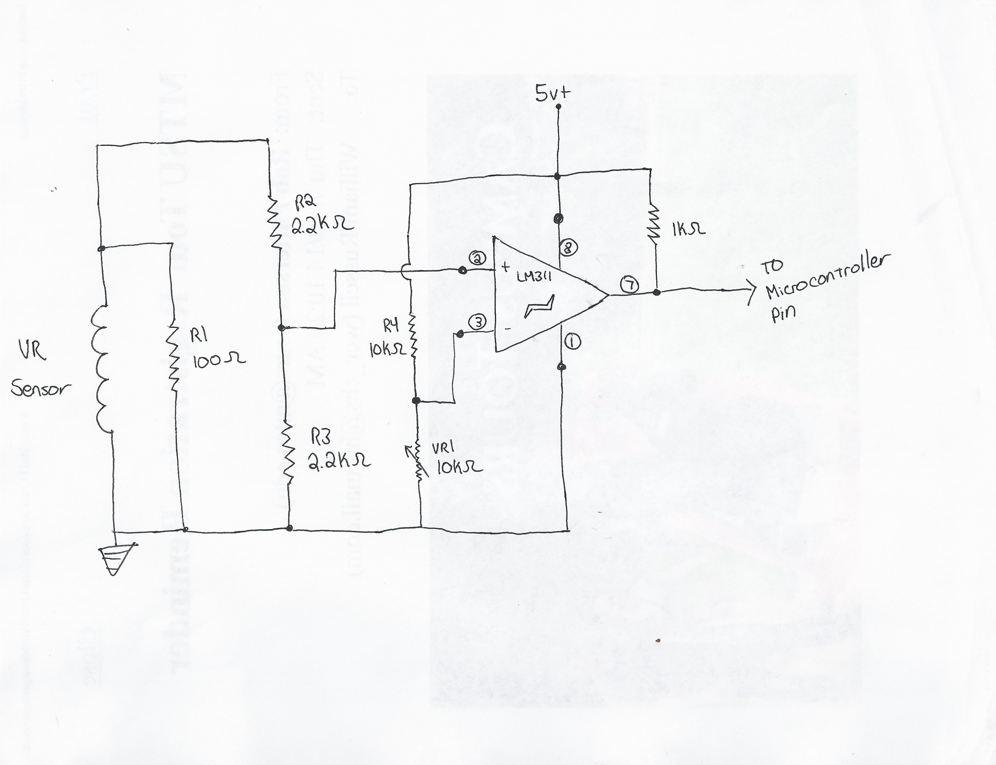
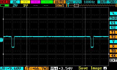
Ok so I came up with a circuit using a voltage divider and a voltage comparator. It works but I dont know what will happen at higher RPMs. I got a schematic and an oscilloscope reading of the output. Tell me what you guys think cause its something I feel like I just threw together without understanding it all.pi
Just in case ... another suggestion would be to try an photodarlington opto-isolator FOD852
AC input photocoupler (responds to both positive and negative impulses) PS2505-1
EDIT: Comment - I haven't used the LM311 comparator, but I see that its differential input voltage range is ±30V ... I would check to see that this is not exceeded on it's input terminals.
what is the magnet polarity? because the voltage from the coil will be AC not DC like a generator output so adding a full wave rectifier bridge before the voltage divider could be a good idea I think.
Or a "clamp diode" anode to the ground and cathode to the operational amplifier input after the voltage divider.
if the voltage from the coil comes negative at the input, under the OP ground you could have "latch up" (i'm searching the good term) problems.
edit: phase reversal is the good term
example:
4.1 Inputs 4.1.1 PHASE REVERSAL The MCP601/1R/2/3/4 op amp is designed to prevent phase reversal when the input pins exceed the supply voltages. Figure 2-34 shows the input voltage exceeding the supply voltage without any phase reversal.
Same thing for the V+ supply rail. so perhaps your voltage divider is not sufficient at higher speed (higher voltage) and you have the phase reversal phenomenon.
Ok I know I'm not exceeding the input voltage just turning the engine over with the starter and the spark plug out (around 700 RPMs if my oscilloscope is correct). Its not currently running so there's no way I can get a reading on what its doing at higher RPMs. Ill just have to get it running to find out I guess. If I find the voltage too high or burn up the chip I'll try what Genesis recommended and add a full wave rectifier bridge. Also Dlloyd I really like your photodarling optocoupler idea, Its really simple and doesn't take a bunch of components to construct. The only problem is I dont have one and I'm trying to stick to components that I have on hand. Thanks for your inputs guys I really appreciate it and I'll get back to you when I get it running. Now to figure out how to program the Arduino to read RPM!
I agree with that.
the photocoupler option with PS2505 could work but: with 10K load resistance at the output, 10K for the led current limiting and a CTR within 80-600 (darlington output)
we have:
for the output
Ic = 5/10K = 500uA
CTR= Ic/If -> If = 500uA/CTR(typ) = 500uA/300 = 1.6nA for the diode
so the input voltage will be Rled * 1.6nA + Vled = 10K * 1.6nA + 1.2 = 1.216v
yes it's a the theory but with this circuit it will be more a zero crossing detector because over 1.216V of input voltage the output signal will be high at the arduino port. (and I did the calculations with 5v level not the lower "Vth high" of the arduino input port)
the frequency response with the 10K load will be a problem too because the switching speed is limited by the load resistance. (10KHz with 1K of load and CTR not derated so much lower frequency with 10K)
so the Rload at the output should be a lower value to increase the minimum led current at the input and the circuit response.
But as LarryD said there's will be no more adjustment possible.
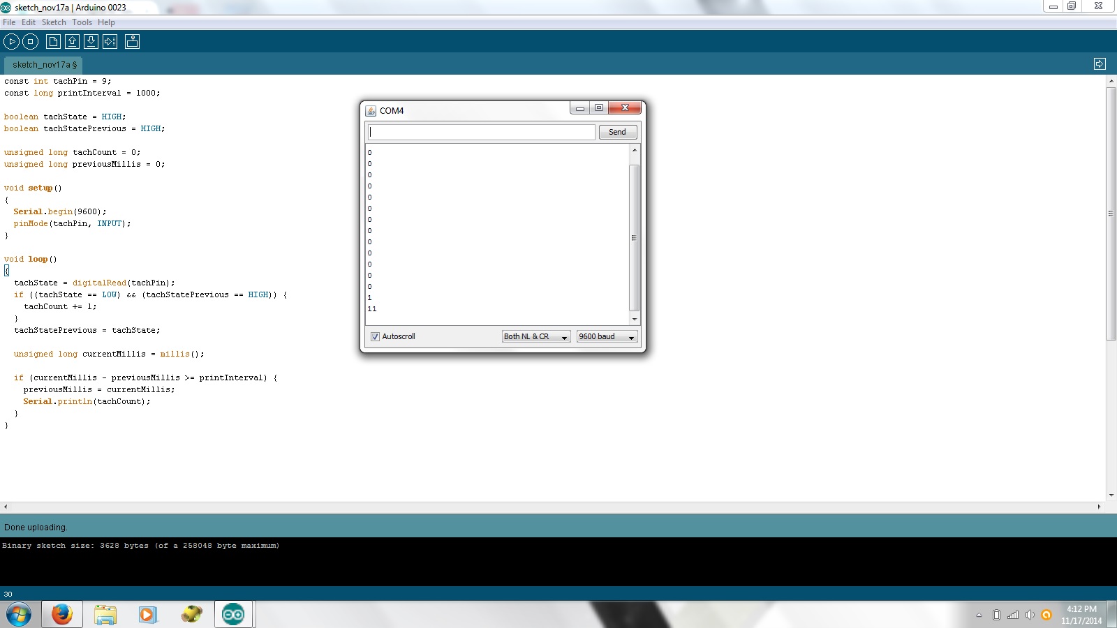
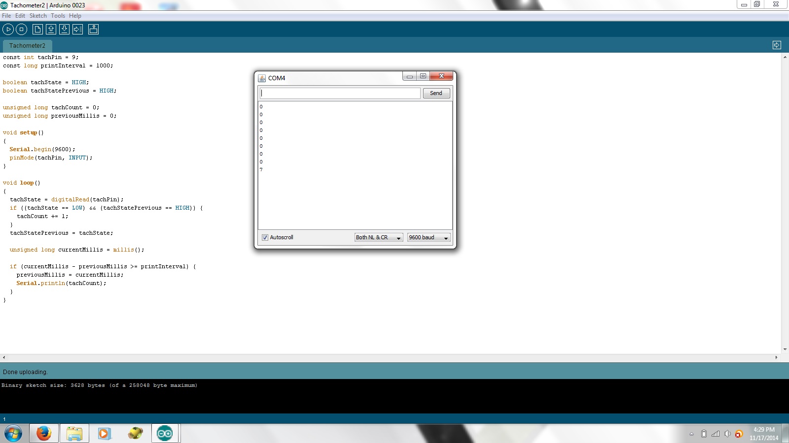
Ok so I wrote some simple code to see if it works but I'm having some trouble. Im using the serial monitor to see if the pin is changing states or not. It seems to work fine until the state of the pin starts changing. I might pick it up once or twice before it seems like the Arduino crashes (tx light quits flashing and I dont get anymore values from the serial monitor). The pin is normally high and I know its sitting right at 5 volts. So is this a hardware issue or a coding issue? I've tried the code several different ways but I keep getting the same one or two pulses and it crashes (I think?). When I unplug and replug the Arduino in, it stays in its "crashed" state. I have to reflash it to get readings again. Anybody got a clue as to whats happening?
Your print statements are executed too many times at once and at a slow rate (9600 baud).
Try this, where falling edges are counted and printing of tachCount occurs only once per second. I would suggest changing the baud rate to 115200 so fewer falling edges are missed while printing when the rpm is at a high rate.
Here, the iteration speed of the loop will be very high. The MPU only needs to increment the tachCount variable when a falling edge is detected and it only needs to print the result just once per second. Otherwise, it just keeps spinning through the loop looking for something to do.
Genesis92:
the best is to use the input pin as an interrupt to avoid missing pulse. like for a rotary encoder
I actually already tried that. It does the EXACT same thing my current sketch does. I get one or two readings when the circuit goes low and it crashes. No more tx flashing, no more serial monitor, and the board has to be flashed to work again. I'm not having any problems missing the pulse its that when the pulse goes low, it crashes.
dlloyd, I'll give your code a shot tomorrow and see what happens. I'm starting to think this is a hardware issue though.
Just some thought: What would happen if I'm getting a negative voltage on my input pin?
strange, a simple reset does not restart the board? perhaps a high voltage glitch goes to the +5v arduino board.
can you draw the complete schematic diagram? or its always this one: link
the ground is common to the arduino board?
Just some thought: What would happen if I'm getting a negative voltage on my input pin?
I don't believe this is the issue because a negative voltage of such severity that crashes the Arduino would most surely have destroyed it's input or more. Note that the LM311 is connected in single supply mode with 5V and GND, it has internal I/O protection diodes and so does the Arduino.
I believe as the signal crosses the refrence point, the LM311 could momentarily burst into oscillation (as mentioned in the datasheet). To prevent this, add hysteresis by connecting a feedback resistor of 510K from pin 7 to pin 3 of the LM311.
With the code provided, the iteration speed should be well above several kHz, so in terms of monitoring the input, this would represent a max. rpm of above 120,000. Of course this is just meant as a starting point to test the input. In your final solution you may need to use an interrupt. I left the print speed at 9600 to start, but changing it to 115200 would be an improvement.
Genesis92:
strange, a simple reset does not restart the board? perhaps a high voltage glitch goes to the +5v arduino board.
can you draw the complete schematic diagram? or its always this one: link
the ground is common to the arduino board?
Reset does not work after it has crashed. The only way I have found to get it to work again is to flash it again. I am using the same schematic and ground is always common between my protoboard and the microcontroller.
dlloyd:
I don't believe this is the issue because a negative voltage of such severity that crashes the Arduino would most surely have destroyed it's input or more. Note that the LM311 is connected in single supply mode with 5V and GND, it has internal I/O protection diodes and so does the Arduino.
I believe as the signal crosses the refrence point, the LM311 could momentarily burst into oscillation (as mentioned in the datasheet). To prevent this, add hysteresis by connecting a feedback resistor of 510K from pin 7 to pin 3 of the LM311.
With the code provided, the iteration speed should be well above several kHz, so in terms of monitoring the input, this would represent a max. rpm of above 120,000. Of course this is just meant as a starting point to test the input. In your final solution you may need to use an interrupt. I left the print speed at 9600 to start, but changing it to 115200 would be an improvement.
I didnt have a 510k resistor so I used a 560k instead and I tried your code as well but I still get the same thing.