Automated Watering System Issue

Hi,

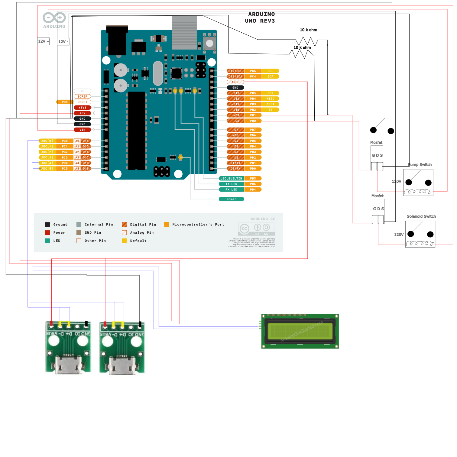
Below is the wiring diagram that I have created and the code that I have written:


//include the liquid crystal library code
#include <LiquidCrystal_I2C.h>

LiquidCrystal_I2C lcd(0x27, 16, 2); // I2C address 0x27, 16 column and 2 rows

int data1 = A0; //analog pin 1
int data2 = A1; //analog pin 2
int LVL = 7; //digital input 7 is the liquid level switch
int pump = 8; //digital output pin 8 is the water pump
int valve = 9; //digital output pin 9 is the valve
int moisture =600; //set switching value for soil moisture


void setup() {
  
lcd.init(); //initialize the lcd
lcd.backlight(); //open the backlight 
  
Serial.begin(9600); // set sample rate  
lcd.begin(16,2); //set LCD screen size
lcd.clear(); //clear LCD screen

//Set analog and digital inputs and outputs 
pinMode(data1, INPUT);
pinMode(data2, INPUT);
pinMode(LVL, INPUT_PULLUP);
pinMode(pump, OUTPUT);
pinMode(valve, OUTPUT);
}

void loop() {

  int sensor1 = analogRead(data1); //Read sensor 1 output
  int sensor2 = analogRead(data2); //Read sensor 2 output
  lcd.setCursor(0,0); //Sets cursor to col 0 row 0
  lcd.print("Sen1:");; //prints Sensor 1 on LCD
  lcd.print(analogRead(data1)); //Prints data1 on LCD
  lcd.setCursor(0,1); //Sets cursor to col 1 row 2
  lcd.print("Sen2:"); //Prints Sensor2 value on LCD
  lcd.print(analogRead(data2)); //Prints data2 on LCD
    if((analogRead(data1)>moisture) && digitalRead(LVL)==HIGH){  //if 1st moisture sensor dry+lvl sensor high, turn on pump
       digitalWrite(pump, HIGH);
       digitalWrite(valve, LOW);
       delay(10000);
    }
      if((analogRead(data2)>moisture) && digitalRead(LVL)==HIGH){ //if 2nd moisture sensor dry+lvl sensor high, turn on pump
       digitalWrite(pump, HIGH);
       digitalWrite(valve, LOW);
       delay(10000);
    }
    if((analogRead(data1)>moisture) && digitalRead(LVL)==LOW){  //if 1st moisture sensor dry+lvl sensor low, open valve
      digitalWrite(valve, HIGH);
      digitalWrite(pump, LOW);
      delay(1000);
    }
    if((analogRead(data2)>moisture) && digitalRead(LVL)==LOW){  //if 2nd moisture sensor dry+lvl sensor low, open valve
      digitalWrite(valve, HIGH);
      digitalWrite(pump, LOW);
      delay(1000);
    }
    else{
      digitalWrite(pump, LOW);
      digitalWrite(valve, LOW);
      delay(1000);
    }
    
    delay(1000); }


The issue that I am having is that when the level sensor that I am using prompts the pump relay to turn on, it will turn on for the desired ten seconds, however it will turn off for one second after the ten second delay, then reactive for another ten seconds. This occurs when both the moisture sensor and level switch should keep the pump on continuously. The level switch that I am using is a switch from Madison linked here: Madison Company - M8000-75 - Miniature Float Switch, PBT, 1/8" NPT, 1.13" sg, 0.75" Float Dia, M8000 Series - Allied Electronics & Automation, part of RS Group

My question is, why does the pump relay go off when it shouldn't? Thank you for the help! Please let me know if I can provide more detail about my wiring, programming, or the issue that I am having.

Thanks,
Dave

Making sure I got this correct. You want the pump to turn on when the reading from the sensor is greater than 600 for 10 seconds. Making the soil more moist. Then the next time around with the soil is even more moist , turn the pump on for another 10 seconds, which makes more moisture?

Another thing, I notice there are a lot of analog reads. Analog reads take a lot of code time. Initially in loop() the analog read is done and stored in sensor, why not use that reading for the entire code and save a small bit of processing time?

If (analogRead(data2) > moisture) && digitalRead(LVL) == HIGH) is true then pump will turn on for 10 seconds:

  if ((analogRead(data2) > moisture) && digitalRead(LVL) == HIGH) { //if 2nd moisture sensor dry+lvl sensor high, turn on pump
    digitalWrite(pump, HIGH);
    digitalWrite(valve, LOW);
    delay(10000);
  }

And if after 10 seconds (analogRead(data2) > moisture) && digitalRead(LVL) == HIGH is still true then the following conditional will fall thru to the else portion turning the pump and valve off for 1 second:

  if ((analogRead(data2) > moisture) && digitalRead(LVL) == LOW) { //if 2nd moisture sensor dry+lvl sensor low, open valve
    digitalWrite(valve, HIGH);
    digitalWrite(pump, LOW);
    delay(1000);
  }
  else {
    digitalWrite(pump, LOW);
    digitalWrite(valve, LOW);
    delay(1000);
  }

Hi Todd,

Thank you for the reply. Yes I think my issue will be resolved by simply changing my else statement to an if statement. My intention is to have the pump run continuously until the moisture sensor indicates that the soil is wet/moisture reading becomes low enough. Thank you both for replying so quickly and helpfully!

Hi all,

So I changed the "else" statement to an "if" statement but that did not resolve the issue. Any ideas why the switching would still be momentary in the loop? This is now occurring for both the valve and pump relays. In other words, when the sensor levels trigger each, they will remain triggered for the time delay time, but then shutoff after.

Thanks,
Dave

You have a rather convoluted sequence of if statements.

The 'else' condition is dependent on only one of the moisture sensors, so the pump/valve can be turning on based on one sensor, them be turned off based on the other sensor.

Combining the logic of all the if statements, I get something like this:

void loop() {
  int sensor1 = analogRead(data1); //Read sensor 1 output
  int sensor2 = analogRead(data2); //Read sensor 2 output
  lcd.setCursor(0, 0); //Sets cursor to col 0 row 0
  lcd.print("Sen1:");; //prints Sensor 1 on LCD
  lcd.print(sensor1); //Prints data1 on LCD
  lcd.setCursor(0, 1); //Sets cursor to col 1 row 2
  lcd.print("Sen2:"); //Prints Sensor2 value on LCD
  lcd.print(sensor2); //Prints data2 on LCD
  if ((sensor1 > moisture) || (sensor2 > moisture)) { //if 1st OR 2nd moisture sensor dry
    if (digitalRead(LVL) == HIGH) { //lvl sensor high, turn on pump
      digitalWrite(pump, HIGH);
      digitalWrite(valve, LOW);
    } else {                        //lvl sensor low, open valve
      digitalWrite(valve, HIGH);
      digitalWrite(pump, LOW);
    }
    delay(10000);
  } else { //both moisture sensor moist, turn off pump and valve
    digitalWrite(pump, LOW);
    digitalWrite(valve, LOW);
    delay(1000);
  }
  delay(1000);
}

Seems like a lot of delays, not sure why you need an extra delay when turning off the pump/valve.

Can you post a real schematic. Powering modules with AREF is a NoNo. The lines are hard to follow. Also post links to each of the hardware items showing "Technical Information".

Here are links to components that I purchased:

Moisture Sensors

Float Switch

I will post an updated, more clear wiring diagram at some point. If you have specific questions about what wires connect where I can answer them in a piece wise manner

Mosfet

I uploaded the program that was sent over that deleted the unnecessary delays and now it works as intended. Thank you all for the help!

I am in no hurry so I will wait for the schematic.


Updated picture with different wire colors to better distinguish between the wires in question

This topic was automatically closed 180 days after the last reply. New replies are no longer allowed.