I got a quite simple question which i am not able to answer because i dont have nothing to measure Volt and Ampere in my circuit.
I have seen different simple circuits with LEDs and Resistors. Sometimes the Resistor gets placed in front of the LED close to the plus and sometimes it gets placed behind the LED. I am not talking about a Pull Down Resistor. My concern is a normal "pre-resistor". I thought i have to place it in front, "pre", to get the right current for a LED oder what piece i ever use. But i also see this "post" placement and i am worried why this is working and how this is working?
I thought the resistor has to "split" the current in fornt of the LED and not behind it.
So now my questions:
Does it matter, if i place the pre-resistor pre or post?
If yes, why?
I am gonna add two pictures explaining the difference.
In picture 2, i guess the 4 resistors are PULL DOWN? Right?
Nevertheless whats in the pictures, does it generally matter if the resistor is "pre" or "post"?
It makes no difference if the current limiting resistor on an led is on either side: the same flow goes through both components.
In the bottom pic, the resistor on the switch is a pull down, forcing the i/o pin to ground until it's pressed. But the idea of the series resistors on the LEDs as "pull downs" (or "ups" for that matter) is meaningless.
It's not important if you put it behind it for turning it on . I've seen many people do this - the resistor won't let lots of current to go to GND so some part of current doesn't come (current wants to go from + to - (voltage to gnd)) another example , instead of a resistor , place a push-button ; the current won't go unless you push the buttons which opens the way for GND .
But there is still one question left:
That means that whatever electronical piece i insert into my circuit, a pre-resistor is just a name and does not have to be placed close to "+" (pre), it can also be placed behind, close to GND, and would still fullfill the same work?
So am i right, that this means, if i place a resistor behind an LED, it doesnt matter where i measure the voltage, in front of or behind the resistor appears the same voltage?
Greetings Chris.
Edit:
I always thought, that the current would be higher until the resistor and fall down behind the resistor :).
No, if you have two components in a line, in series, think about where the current goes: it HAS to go through both, so it must be the same.
But the voltage differs depending on where you read it: if you start with 5V, you get a voltage drop of (say) 3V across the resistor and (say) 2V across the LED. So the sequence depends in the sense that you will get a different voltage value at the join betwen them, but the current must be the same.
Thank you for the detailed explanation.
But this actually is not my problem or I just dont get it right.
I know the rules and i know this behaviour and also the math behind.
I just think i have a small logical misunderstanding...
Look at your circuit in the Foto and think about my question, maybe you then understand my logical problem:
What would happen if you swap the Resistor with the Led?
Now the Led would be connected to plus directly and the resistor would lead to Ground.
So if you would measure the Voltage across the LED now, you would not get a value of 2V, you would measure 5V, am I wrong?
My "brain" tells me, that it has to matter where i place the resistor, because the Voltage gets reduced by a resistor. I than think, the V value sinks directly after the Resistor about 3V and in front of the resistor the voltage stays like given (5V).
Am i just thininkg wrong?
I understand, that the Voltage falls down across the resistor. But what happens directly in front or behind the resistor?
Or "IS" there no "in front" or "behind"?
So only the current matters? And the current for the whole circuit is given through the addition of the resistors.
-> I total = U total / R total?
What would happen if you swap the Resistor with the Led?
I did do exactly that: one set shows the LED on the left by the black power wire, the other it's on the right by the red. The voltage drop across the resistor is 3V in both cases, across the LED it's 2 in both.
But hang on, I'll hook up that circuit again with some bare wires too, so you can see how what happens just in "front" and just "behind"
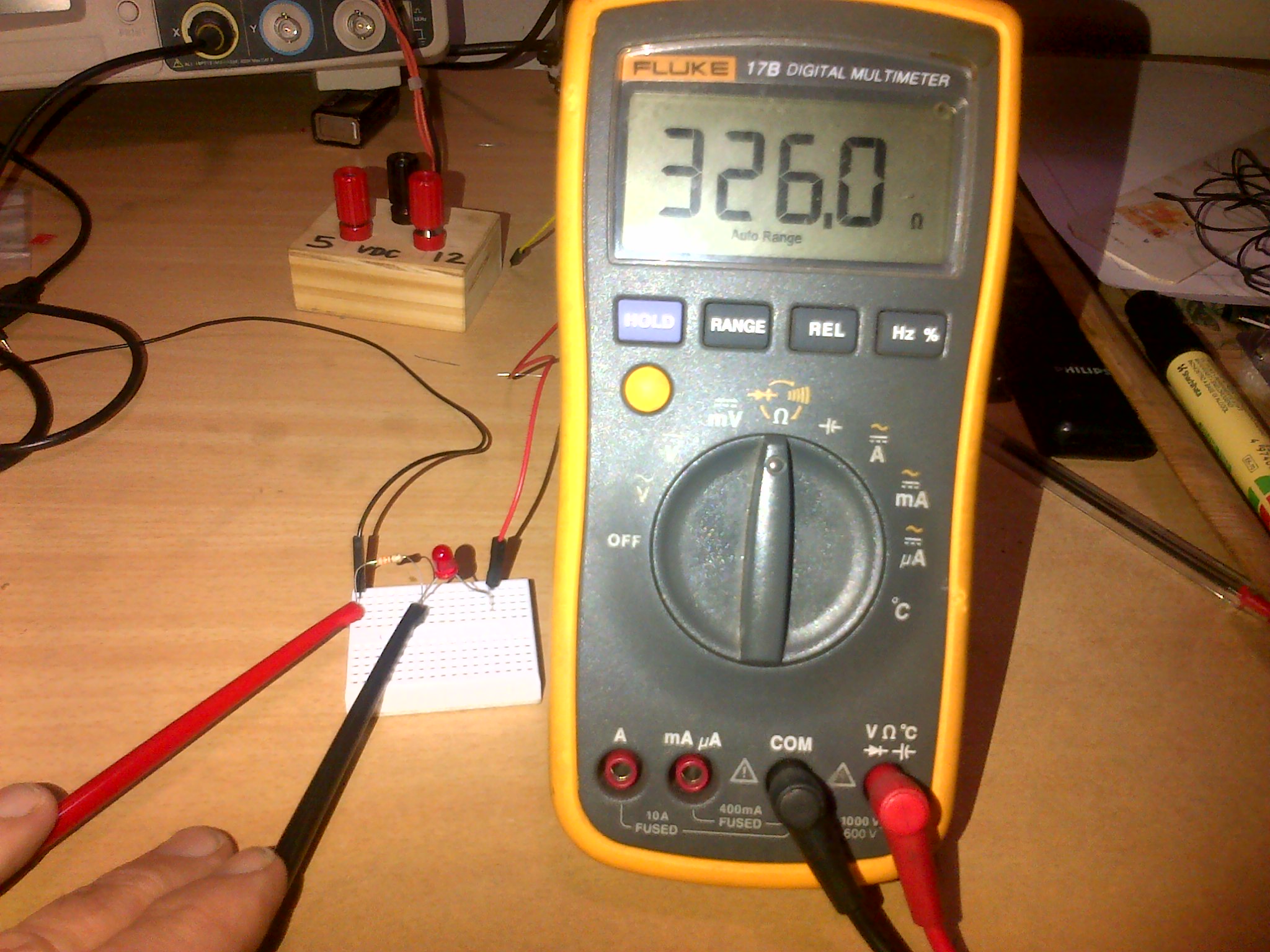
They show 3 resistors in series: the outer 2 are zero ohm, the middle one is a 470 (measured 463 actually).
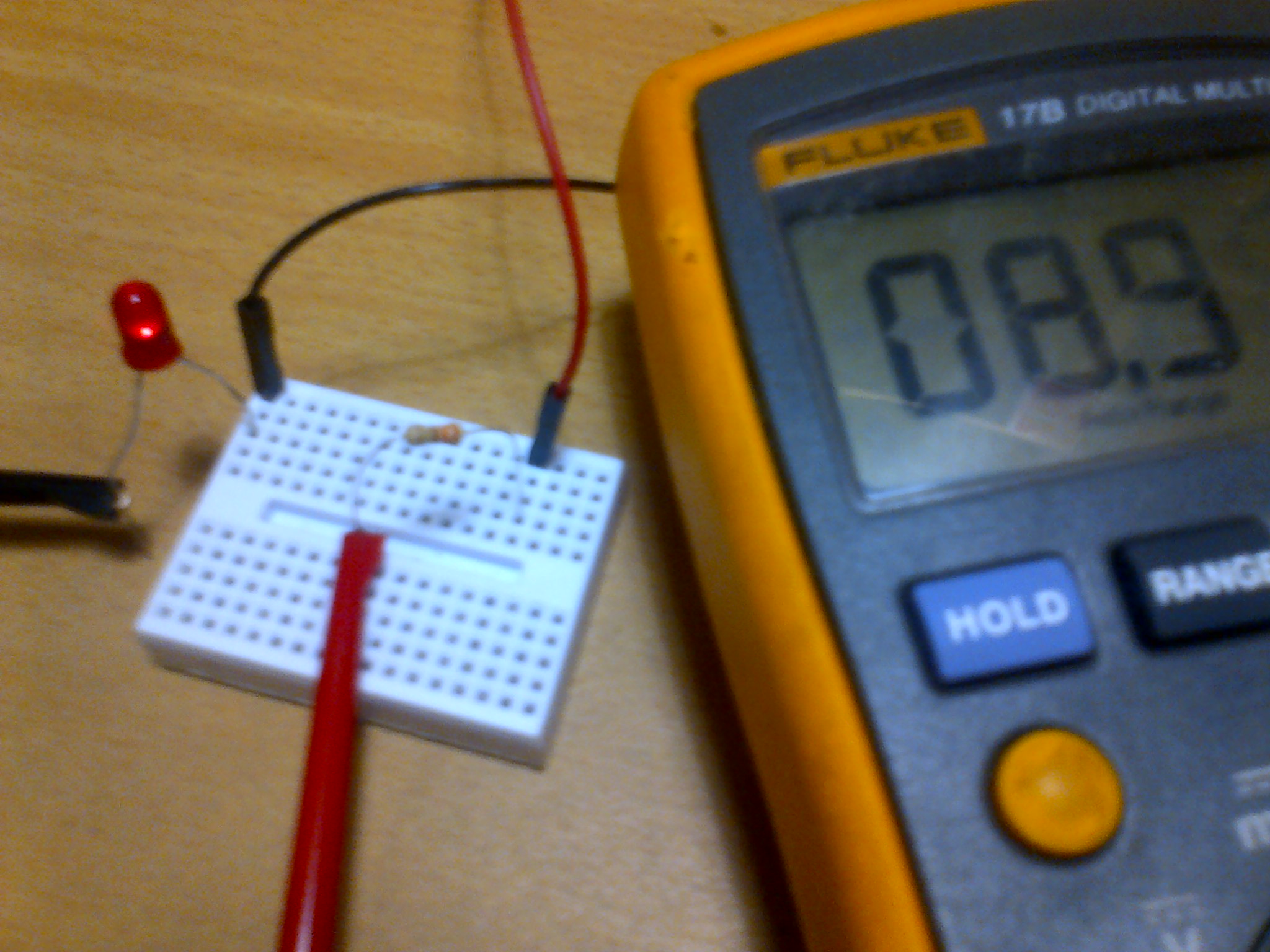
The 4 pics in order from the top show:
0V at the left of the first 0 resistor, which makes sense: the meter probe is actually on the 5V -ve supply
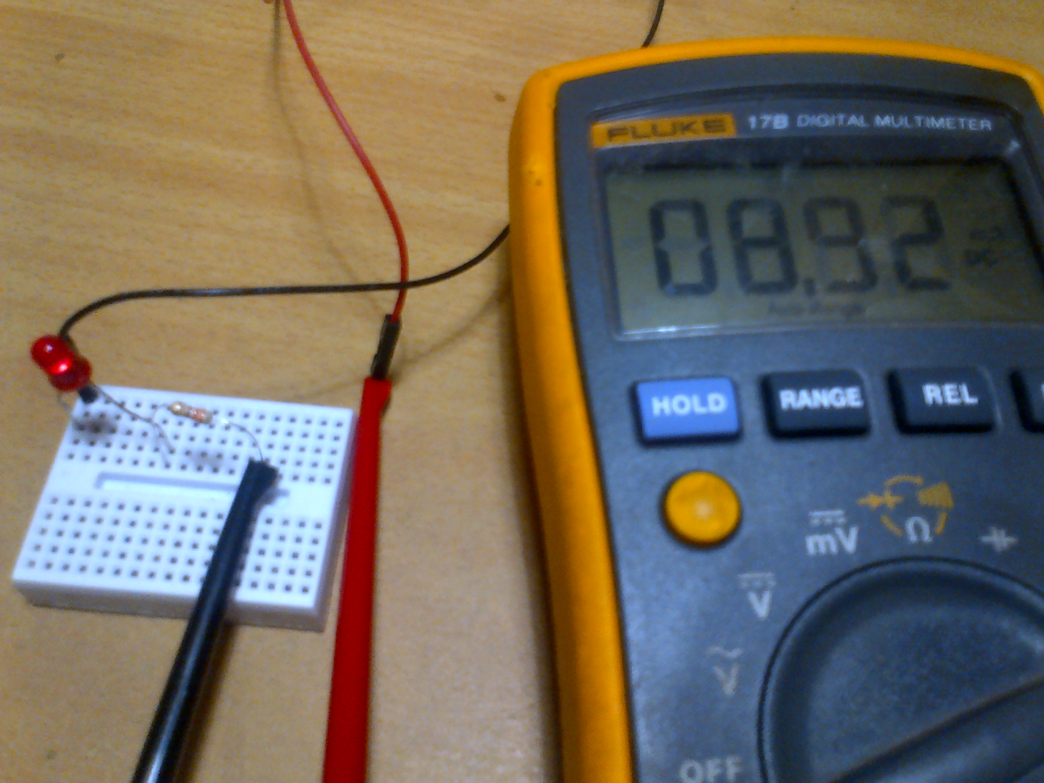
0V at the right of the first 0 resistor, which is the left of the 470. That makes sense too: there is no voltage drop over the 0 resistor, so it's still basically the supply -ve.
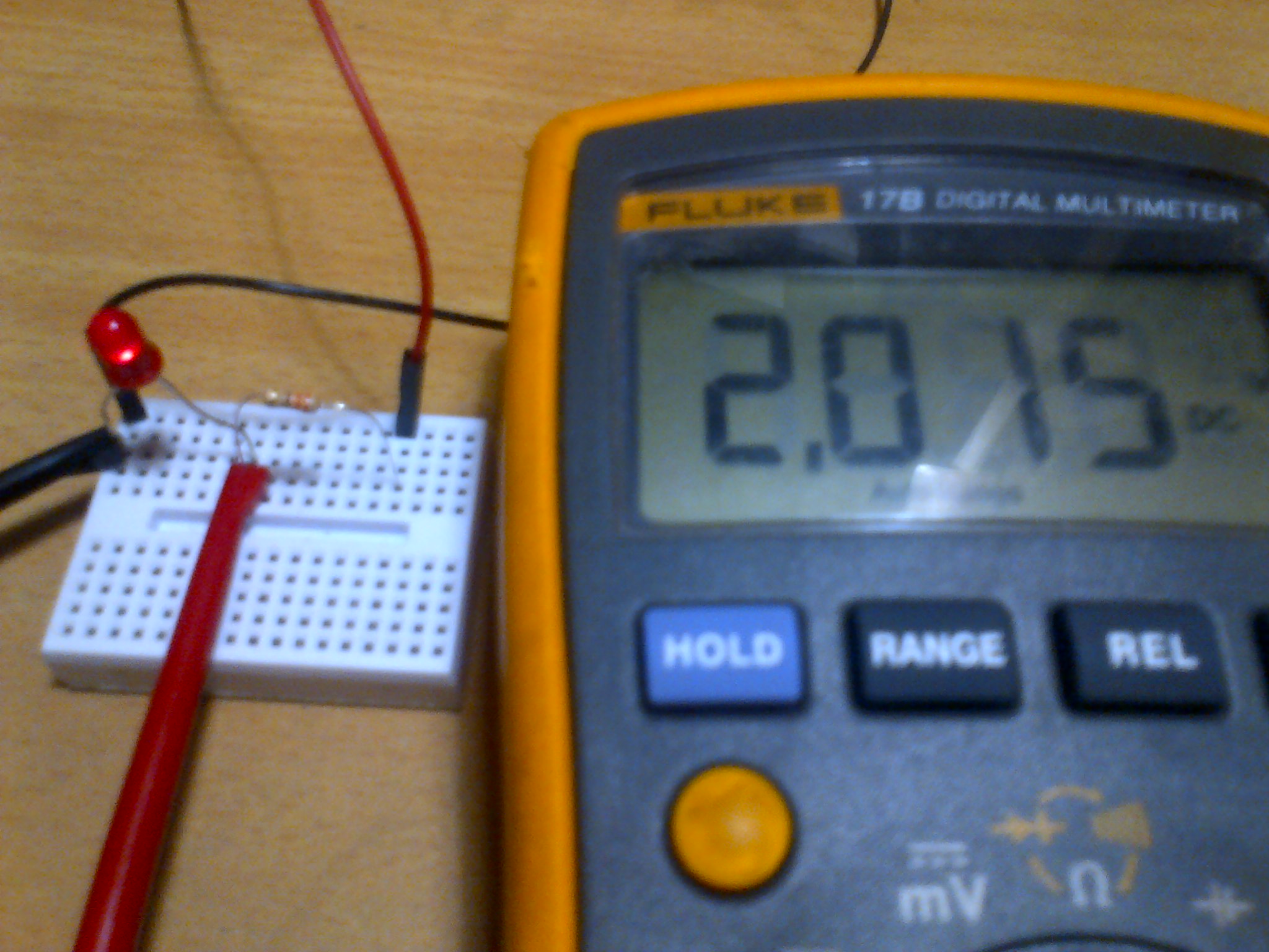
5V on the right side of the 470, which is the left of the second 0R. Let's come back to this below.
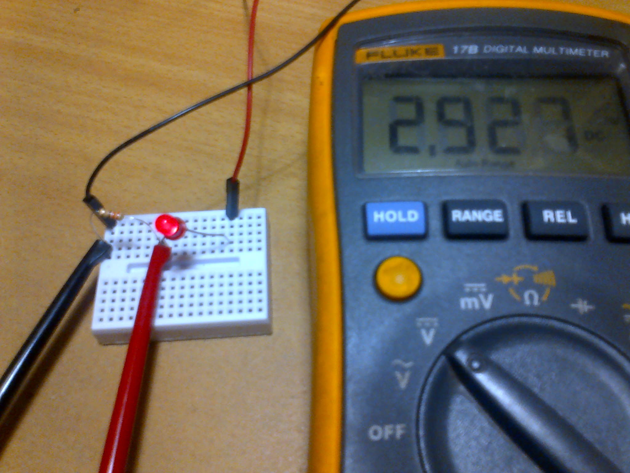
5V on the right of the second 0R, which is actually the supply +ve so that makes sense.
So what happened in there?
Well we had 5V at the extreme right, on the supply. We had 5V just to the right of the 470, ie just "after" the right hand 0R, coming from the 5V side.
Just to the left ofthe 470, we had 0V, with no drop across the lefthand 0R. So clearly the 5V which was present just to the right of the 470R had gone by its left hand side.
That 5V was dropped by the resistor, which will have warmed up a tiny amount and produced a tiny amount of power.
Here's the pics, in left to right order from the top.
At LAST: a use for a 0R resistor whoop whoop.
edit: I didn't resize the photos, there's no need to open them, the thumbnails show what's going on I reckon.
edit edit: except that the bloody thumbnails don't work anymore grrrrrrrr
I understand, that the Voltage falls down across the resistor. But what happens directly in front or behind the resistor?
Or "IS" there no "in front" or "behind"?
Correct, there "IS" there no "in front" or "behind".
In a series circuit the current is identical at any point in that circuit, so component placement has no effect. The total series resistance 'sets' the current flow at any given source voltage.
From the pov of current that's true, but voltage differs from one side of a component to the other. But for voltage it may be better to think of "above" and "below" maybe, as high and low, rather than "before" and "after". And of course a "before" and "after" discussion will then open the Pandora's Box of conventional vs electron flow, so I won't mention that at all. Oh, wait.....
in fact, I'm going to redo my circuit above as a vertical collection, with 5V at the top and 0V at the bottom.
i finally got it. Thx to you. It just had been this extreme sequential thinking in my poor little brain lol.
It all makes sense now. I also had not looked up all your pictures before with led-resi and vise verca.
But nevertheless the final thing to make me understand, had been the combination of both.
The easy 0R example and the swap Led - Resistor thing...
Thank you very much. I really appreciate your patience with me in that case.
Tough birth.
You're welcome... and that will teach you to read the responses properly
I'm bookmarking this thread: there are often questions along the lines of "surely the resistor must be in front to throttle the current for the led?" kind of thing, and I'll just point to my photos here.