Post your code with the serial prints in it.
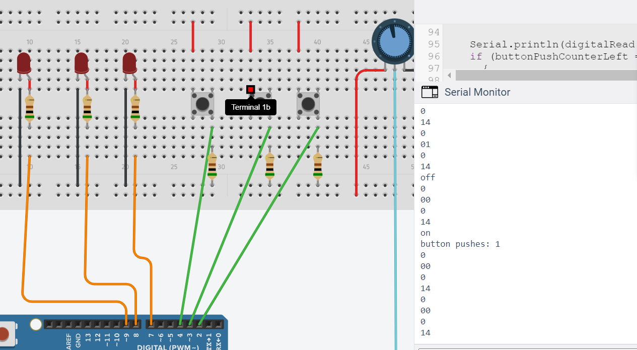
   Serial.println(digitalRead(button1));
  if (buttonPushCounterLeft == 1)
     {
    digitalWrite(led3, HIGH);
    delay (potValue);
    digitalWrite(led3, LOW);
    delay (potValue);
     }
  Serial.println(digitalRead(button2));
  if (buttonPushCounterDominant == 1)
  {
    digitalWrite(led3, LOW);
    digitalWrite(led1, LOW);
  }
  Serial.println(digitalRead(button3));
  if (buttonPushCounterRight == 1)
  {
    digitalWrite(led1, HIGH);
    delay (potValue);
    digitalWrite(led1, LOW);
    delay (potValue);
  }
The button2 wont shut off the leds
Put a serial print before this line:
digitalWrite(led3, HIGH);
No. Right above the line I showed you.
Serial.println(led3);
digitalWrite(led3, HIGH);
Surely you already know what pin number that is
Got no idea what to do
1. Left Button is Button3 and is connected with DPin-4. Correct?
2. Right Button is Button1 and is connected with DPin-2. Correct?
3. Middle Button is Button2 and is connected with DPin-3. Correct?
4. If you psuh (once) either the Left Button (Button3) or Right Button (Button1), all three the LEDs will blink continuously. Correct?
5. If you push (once) the Middle Button (Button2), then the LEDs will stop blinking. Correct?
6. I have compiled and uploaded pur sketch in my UNO. The LEDs do blink when I press Left Button; but, they do not blink when I press Right Button. The program also does not respoond to Middle Button to stop blinking of LEDs.
7. The delay(potValue) code should be replaced by the following codes:
unsigned int timeDelay; //global declaration
timeDelay = map(potValue, 0, 1023, 0, 5000); //timeDelay varies by 0 to 5 sec as pot is rotated
delay(timeDelay);
Run the following simple sketch to establish your basic idea and then modify it to meet your advanced ideas.
// C++ code
//
const byte button3 = 4;
const byte button1 = 2;
const byte button2 = 3;
const int led1 = 9;
const int led2 = 8;
const int led3 = 7;

unsigned int delayTime;

void setup()
{
  pinMode(button1, INPUT_PULLUP);
  pinMode(button2, INPUT_PULLUP);
  pinMode(button3, INPUT_PULLUP);
  pinMode(led3, OUTPUT);
  pinMode(led2, OUTPUT);
  pinMode(led1, OUTPUT);
  Serial.begin(9600);
}

void loop()
{
  int potValue = analogRead (A0);
  delayTime = map(potValue, 0, 1023, 0, 5000): // 0 to 5 sec timeDelay as the Pot is rotated
  if ((digitalRead(button1) == LOW) || (digitalRead(button3) == LOW))
  {
    do
    {
      digitalWrite(led3, HIGH);
      delay(1000);
      digitalWrite(led3, LOW);
      delay(1000);
    }
    while (digitalRead(button2) != LOW);  //stop blinking when button2 is closed
  }
}
Fix the print that Awol pointed out to be a simple "here I am". The resulting serial output in the monitor should give you a clue as to what is happening.
Are you running this in a simulation, or on real hardware?
On a simulation on Tinkercad
This topic was automatically closed 120 days after the last reply. New replies are no longer allowed.