I expect it's for visible light filtering. Ir leds produce also visible light and in some situations you want to filter it out. One reason is to make it invisible (stealth) for human eye. Another might be advanced color night vision cameras, that need to use different level of filtering on source and on sensor.
1 Like
LEDs can produce electricity if light is directed into them. Maybe the dark material blocks light, too?

2 Likes
Yeah. Then will be first one for that camera.
Guys, I also have spare Hikvision one-DS-2CD2142FWD-I (W)(S) which is now temporary installed on Dahua place. It have stronger IR light which easy see with naked eye in half light room. That camera have for sale.

This could be the strategy of saying "we see you" without putting a sign out that says, "we are watching you"
1 Like
You always see ir-illumination in image taken with camera. But for naked eye there can be huge difference between one and another. "Normal" transparent 850nm ir-leds are clearly visible for eye because of lower wavelengths they produce (red). Some filtering and they don't pop up on eyes anymore...
Oh yes, I forgot explain picture above.
On picture above red lights from naked eye are the same like you watching at picture above (taken from phone), for Hikvision.
But for Dahua dome, as I remember, it was barely see or nothing with the naked eye in the dark. They are darker.
Ok, I found a seller "alive" on AliExpress and contacted him about IR. Waiting reply. But not believe that he have that IR board.
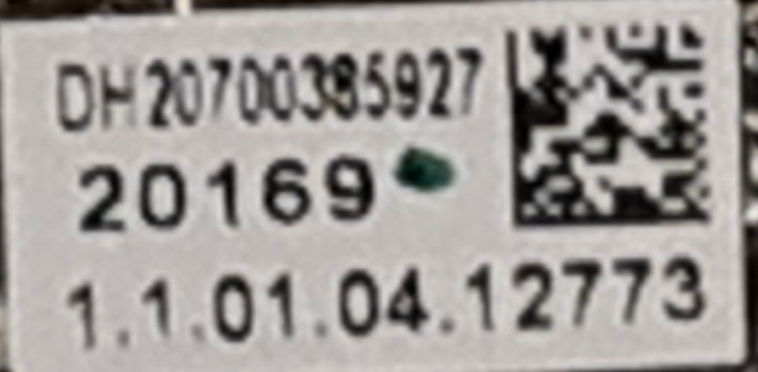
Are the LEDs type write somewhere on the board? I can zoom few places where is some kind of numbers...
OK, I understand. Well, make the schematic. That's where it all starts. from that point you can decide how to best repair or replace this light source.
Probably not. But you have the board there with you, so this is really a question for you, isn't it?
Post pics. But no, I don't think LED type is likely to be listed.
Again, make the schematic diagram of the light source so you know how the LEDs are connected to each other and to the main PCB of the camera. It will also be useful to know as much as possible about the LED driver on the main PCB, so you would ideally trace the contacts for the LEDs to the main PCB and then work out where the driver section is. Then make a schematic of that, too. If you're lucky, there's a way to work out the total current that's run through the LED array.
2 Likes
Ok. I never draw schematic from the other device. But I can make a simple one, just draw which pins are connected.
So, with multimerer in position "diode", I suppose that I need to place a probe on "first" pin, and with another probe test continuity on second pin, third, fourth, etc... And repeat that 23 times?(or just 11, if you sure that 12 big and 12 small diodes must be separate?). And draw which pins are connected.
Then place probe on "second" pin, and with another probe test continuity on first pin, third, fourth,etc... And repeat that 23 times.
Then place probe on "third" pin, and with another probe test continuity on first pin, second, fourth,etc... And repeat that 23 times.
That's a good first step. The second stage is to position the diodes in your drawing in a logical way that represents their functional interaction. This will result in a readable schematic. So start with a connection diagram that's more or less a one-on-one representation of the physical device, and then work that into a functional schematic.
You determine connections with the continuity setting on your DMM. Many DMM's 'beep' in this mode, or a light comes on on the device. On most DMM's, the continuity setting is combined with either diode testing or with a low-value resistance testing. You use this setting to determine which pins on the diodes are connected together.
You can use the diode setting on your DMM to verify if the diodes work. They should give a logical forward voltage (around 1.5V) in one direction and an open circuit/high impedance in the other direction.
So for clarity's sake: testing the correct operation of the diodes is a separate activity from determining how the diodes are connected together.
Yeah, something like that. Be systematic, in any case. If you keep in mind how the diodes are probably connected (i.e. there are likely to be multiple strings of series-connected diodes, with the strings being connected in parallel), you can usually spot the logic as you go about. If no logic appears, then the only thing you can do is systematically check all possible combinations.
1 Like
Thank you.
Can I unsolder all diodes out before test? Will be easier to test.
Anyway we will change whole fresh set diodes, because we don't know same type/color/filter of LED's.
Here are dimensions of that two types diodes and marks on board, maybe someone can recognize something:

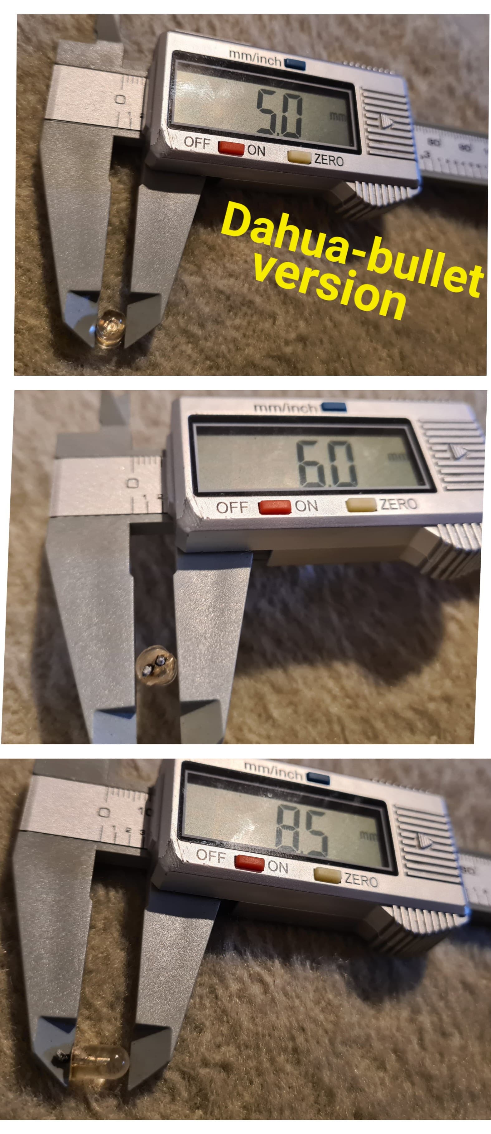


EDIT: If we put board on light and pull out LEDs, we can clearly see all connections
Can I unsolder all diodes out before test?
.
.
.
.
.
.
.
.
.
.
.
You can, but I don't see why you'd bother.
.
.
.
.
.
.
.
.
.
.
.
How's the schematic coming along?
2 Likes
I have to take them all out anyway. So, better sooner than later.. Right?
Scheme. Now I'm on pin number 13. I found 6 diodes connected on two occasions (6x2). I am expecting two more rows with 6 together to find (6x4=24).
2 pins connected two times.
And 2 pins (1 diode) that isn't connected anywhere? That is strange (Maybe try to put little solder iron on it). Can be possible ![]() ?
?
Note, that's only the first 11. I'll let and draw you know the rest.
Btw sorry about dots in post. They are just to center sentences to be more noticeable because sometimes people in a hurry miss a Post ![]() Anyway, I would remove it after somebody answers me. So you can remove it too to save space on Forum and pages numbers
Anyway, I would remove it after somebody answers me. So you can remove it too to save space on Forum and pages numbers ![]()
I can answer that. Because the IR LEDs actually begin by emitting RED light and then turn to IR. The dark epoxy is to absorb the red visible light. The clear IR LEDs are don't care and will show the visible red for an instant when turned on.
1 Like
Which can be better in dark for picture? And which give "longer" distance brightness in picture? 850 nm? Or maybe they are similar.
I have that small darker in dome camera and in bullet transparent and bigger LEDs. But I think that small LEDs are newer type (dome camera bought later) and maybe stronger.

Assume all of us read and don't miss crucial things.
If you want to ensure we don't, then post only what's relevant.
Probably not.
Post back when you've got the schematic.
1 Like
MY trail cameras all use the clear IR leds.
My discovery was an answer to why all the various animal pictures taken a night showed they were looking at the camera. Then one night I tripped the camera while I was looking in the direction of the camera and could clearly see the red light for an instant.
If your project does not mind if there is an instant red light, then the clear epoxy will give the greatest amount or IR light.
If you are seeing animals that look at the camera, you know why.
2 Likes
I think this is a video setup. And I suspect it's security-related, not so much animal detection.
If security related, I would have one fake/bait-IR-cam with (subtly) visible light and one well-protected, well-hidden IR cam for the real security.
1 Like
I have big problem. One of contact link (how you ever call it) is ripped out.
One part which exist I flipped it with a microscope (picture 4). But missing link around pin.
Would be that ok, or I need to throw the board in the garbage?
When I will solder new diode, would be spread on that link which I flipped and make contact?
Is the PCB board have only that links or they have internally "hidden" contact too?


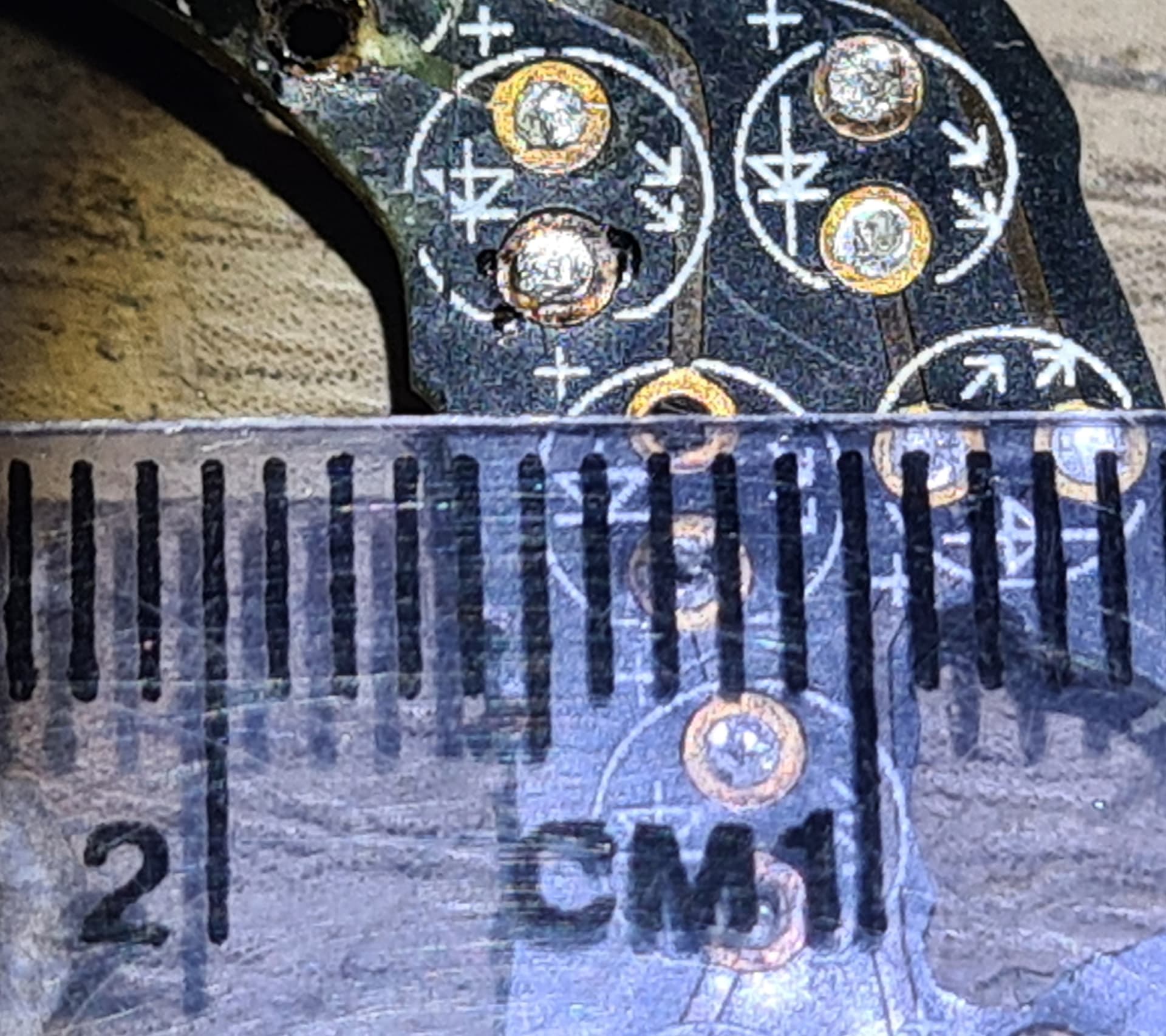
This is how looks normal contacts:
