Kicad is free and works pretty well, only problem is some components aren't there, but adding is easy
The only problem I see is atleast for batchpcb the max size is 15" which also is quite expensive at 2.50$ sq in
not sure about the other places, it may be cheapest to just use perfboard and spend some time wiring
As each display will be driven by a 3- or 4-wire link can't you split the PCBs up?
Rob
What I'm actually looking to do is to make the display "brain" on one or more (thinking less than 3, possibly) main boards, with the inputs, Nano, and display driver chips, and then have a second (or 3rd, in the case of the wider cluster) board that contains all of the actual displays, with ribbon cables (I have a LOT of old IDE hard drive cables) connecting them. I don't think I'm going to have room in the circles (3 7/8" diameter) in the wide cluster to have the chips along with the 7-seg displays, and I know I won't in the smaller cluster (the one with the single 19" wide board).
What I've got drawn up for the displays (on graph paper) is:
Speedometer: 3/4 of the circle's outer diameter ring with T1 LEDs (32 LEDs), 3 digit 7-segment display at .40" digit height, 2 DIP8 4-digit 7-segment displays for the odometer (eBay item... Need small 7-seg displays).
Tachometer: Same as above except only one 4-digit 7-segment display instead of the 3 digit and dual DIP8 displays.
Fuel and vacuum gauges: 10 T1 3/4 LEDs (or T1's, whichever fits and looks the best) in a single row along 1/3 of the remaining 2 circles.
Coolant/air temp and battery voltage: Same as fuel gauge with the addition of a 3-digit 7-seg display, along another 1/3 of each of the remaining circles.
Oil pressure: Same as above except with a 2-digit (may need 2 single displays as I can't find a dual with the same intensity as the others) 7-segment display, along the final 1/3 of the "engine health" circle (oil pressure, coolant temp, manifold vacuum gauge). I could adjust the intensities of each gauge accordingly, but the remaining gauges would be so dim that they would practically go out when I dim the gauges to go with the interior lights when it's night (I usually set the interior dimmer to 50% brightness).
I'm hoping I can fit it all in. I'll continue with Express PCB for the moment to get the layouts figured out (already starting to lay out the PCB's and only need to finish 2 more schematics), and then copy over to whatever program I'll be using to produce the necessary Gerber and layout files.
Guess I'll continue with splitting up the gauges into individual cards. Probably better that way anyways, even though it's going to cost more with more connectors and such. I'll try the KiCAD, I guess, as well. Seems like I'm going to need to make chips in the CAD programs other than ExpressSCH/PCB anyways.
You could use some right angle headers and right angle sockets to connect boards next to each other, it would allow you to have smaller boards that fit together without wires
Okay, I downloaded KiCAD and it took forever to get it going as I had a bit of difficulty figuring out how to set up the libraries and what not, but it's got all of the required schematic layouts and footprints now. I'm almost done drawing up the "brain board", but I am confused on the SPI connections. The Arduino has the connections labeled as SS, SCK, MOSI, and MISO, and the MAX7219's have the usual DIN, DOUT, LOAD, and CLK pins. I think the SCK goes to the CLK pin, but the others I can't figure out. Also, I currently have the DOUT pins of the MAX7219s connected to the DIN on the next 7219. Is this right?
Also, can I use the 5V bus off of the Arduino for all of the chips, or should I use a separate LM7805?
I ordered a Nano off of eBay a couple of hours ago. I suppose it will be here sometime in the next week or so, and then I can go out and get a decent sized breadboard from RadioShack for putting one gauge together at a time and working on the programming, once I get the necessary LED displays.
MOSI -> DIN
MISO -> DOUT of last 7219 (only if you need to read back from the MAX7219s, otherwise nc)
SCK -> CLK
SS -> nc
any IO pin -> LOAD (you control this with your code to load the data after the shifting it done)
I currently have the DOUT pins of the MAX7219s connected to the DIN on the next 7219. Is this right?
Yep.
Rob
you can load as many chips as you want on the Arduino (or any other) voltage regulator up to it's maximum current capacity. That's approx 800ma on the arduino if it's plugged in thru Vin, or 500ma if powered via USB.
Thoughts and opinions on speedometer design are this, semicircular linear bargraph display with fast response time and digital display in the center with a somewhat slower response time such that you don't get the zipping '8' during rapid speed changes. The same philosophy would apply to the tachometer and oil pressure as well, as both parametes can vary widely and rapidly with acceleration.
Well, I don't know about your car, but the oil pressure in mine doesn't vary that much when the engine is hot, maybe about 15 PSI difference between idle and 4000 RPM, and 30 PSI between hot and cold idle (which starts at 70)... May be different since I've rebuilt the lower end.
Once I get into the programming, the update rate on the speedo and tach will be adjusted accordingly.
Got the Nano today (wasn't expecting it for 2 weeks yet). Didn't realize it was so tiny... Just wish the Chinese that shipped it would have put it on one of those foam blocks first to protect the pins (it's bare in an anti-static bag). I'll go out later this week and get a breadboard from RadioShack so that I have some way of getting the pins protected for the moment. Then I'll see about getting a couple MAX7219s and LED displays to get going, probably once my tax papers show up and that gets done.
This might be a useful document toward your goals, I do not know if you already have it or not.
http://esd.cs.ucr.edu/webres/can20.pdf
It is the CAN 2.0 specification.
Okay, I'm bringing this back from the dead...
I have the PCB files and Gerber files done and checked. However, I think I need to make some adjustments to them now that I actually have the cluster they were designed for (93-96 Camaro), so those will need to wait. I do have the KiCAD schematics right here, but could use some help transferring them into pics to post.
One question: I NEED the Maxim MAX7221ENG, for the extended range temps (it gets cold here in the winter) for this project. However, all I can readily find is the CNG series (starts at 0C, 32F on the low end) for cheap (ENGs are typically $16 while the others are like $6). Heck, I can get 10 7219CNGs for that price, but those don't appear to have the SPI interface, according to the datasheet. Question is, what effect does, say, 15F (about -10C, if I'm thinking correctly at about 1.8 degrees F per degree C), have on the chip not rated for that temp?
I still haven't started anything for this yet... I'm still getting info before I start. I ended up replacing the car body in April and have been building it up since, but I'm still a few pieces short.
Bump it up...
Had to completely redo the board files from scratch... Most of the chips on the main board were in spots where they wouldn't fit and I didn't have any mounting holes in yet. And the gauge board had to be completely redone with a different outline (they wasted SO much space on the gauge face with the small window!). As it is, I have a 2-layer board for the gauges and a 4-layer for the brains, I'm thinking about $200 or so between them (until prices go up).
I still don't have a breadboard, LEDs or any MAX7221s. Still waiting on the input for the temp effect between the CNG and ENG chips...
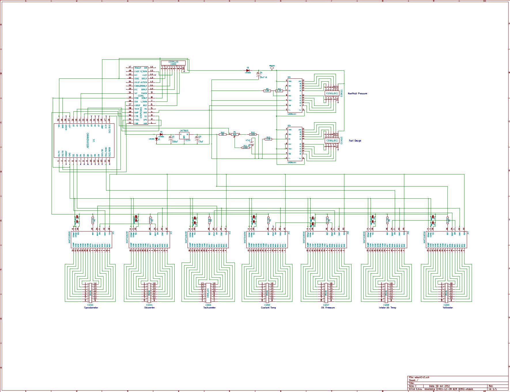
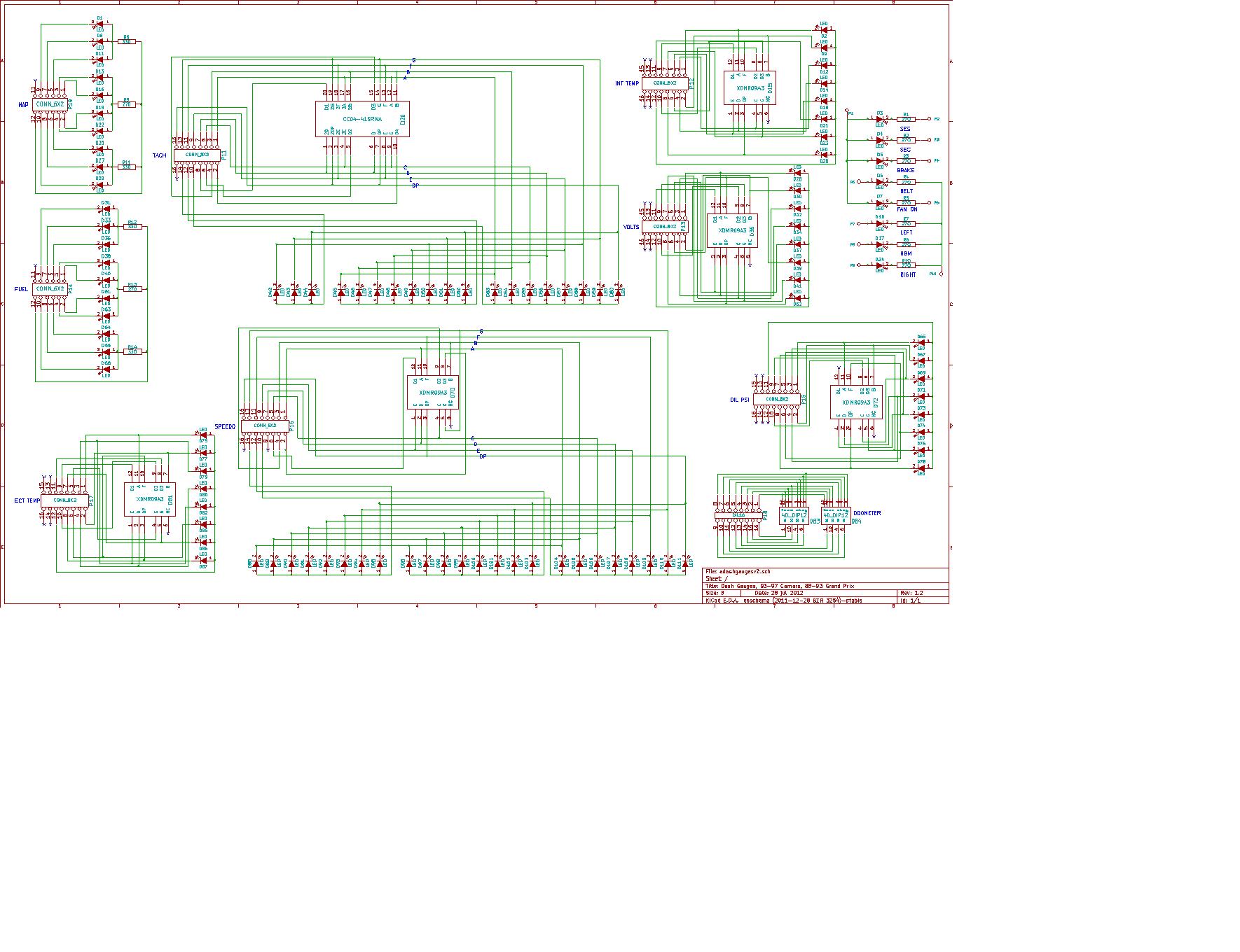
I'm attaching the schematics for the 2 boards... The pinouts on the connectors that run between the boards are identical, pin 1 to 1, pin 12/16 to 12/16, etc.

How about a larger version of the second schematic?
Rob
I'll get another version of the gauge schematic shortly. I will need to completely start over with a new file from KiCAD before I resize it. I didn't think it ended up as small as it did.
I got myself a starter kit from eBay, and it arrived yesterday. I have the MAX7221s ordered, but apparently the Chinese are driving them across the ocean or something... ![]()
Now, I'm confused a bit. With the sample analogRead sketch, I can get a basic potentiometer to work, but when I hook it up to the same "stimulator" used for testing my MegaSquirt II and turn the coolant temp pot, I get nothing but garbage. I'm using the same code as is in the basic sketch, and I'm hooking up the +5V to the +5V line on the stim, and the A0 port to the "CTS" (coolant temp pot) output. I THINK I'm supposed to be reading between close to 0V and 5V. I already know that the factory gauge dives (under 100*F) when the circuit is open and pegs (over 260) when jumpered to ground. My factory manual lists a tool that gauges between 50 ohms (hot) and 1260 (cold).
I'm stuck here as well as the intake temperature.
But, right now, I'd like to get a system voltage reading, between 8 and 18 volts (usual is about 14.7) for the volts gauge. Would a sketch for this be similar to the sample used to read the reference +5V voltage? I'll again be using the pot I got in the starter kit to simulate the proper voltage off of the stim (only 12V source I have right now).
And, I assume, I'm probably going to need some sort of power limiter, since I don't want to fry the Nano, and I already know my alternator can put out more than 20V if the regulator craps out (again, already replaced it once). Any suggestions?
Can it be done
Surely yes. But that's not the challenge.
The challenge for such kind of applications is not to make it work when it works; It is to design for failure: when it fails, it fails safe.
Resized gauge schematic... Don't mind the indicators in the top right... Those are wired specific to the car's harness and are completely independent of the Arduino.
and I already know my alternator can put out more than 20V if the regulator craps out (again, already replaced it once). Any suggestions?
More than that if you get a "load dump" situation (battery lead comes off), that can go > 100v I think.
There are regulators designed to handle that, like the MIC29150/29300/29500/29750 series.
You should probably make a hardened PSU for use in a vehicle, that said most people seem to just hang a regulator off the battery and get away with it.
I'd like to get a system voltage reading, between 8 and 18 volts (usual is about 14.7) for the volts gauge.
Use a voltage divider on the 18v input and read with an ADC pin.
Rob
Well, for the power supply, since I got to thinking about it, I was thinking that the PSU used in the MultiDisplay project would work. Or the one used in the MegaSquirt. I'll have to modify the schematic and board ![]() . I almost think it would be better to modify the board with the MSII PSU since I need a 12V source leading out of the cluster to the alternator (backup sense wire, don't know why it needs to be connected since later models don't have this wire, but...).
. I almost think it would be better to modify the board with the MSII PSU since I need a 12V source leading out of the cluster to the alternator (backup sense wire, don't know why it needs to be connected since later models don't have this wire, but...).
As for the voltmeter, I saw this:
But there doesn't seem to be much info going along with it. I'm assuming that it would be similar to the analogRead sketch?
I have to go out and hook up the battery in the car again so I can find out if the available voltage for the coolant temp and oil pressure senders is 12 or 5 volts so I can go from there. I already listed the coolant temp resistance range, but the oil pressure unit goes from 0 ohms at 0 pressure to 90 ohms at max pressure (which on my factory gauge is 80 PSI, normal max pressure coming out of the oil pump regulator is 70 PSI), and the intake air temp is even weirder, going from 100K at -40F to 450 at 160F (same as engine coolant temp sensor for the ECM, but it won't get that hot).
Also did some basic math for the tach and speedometer:
Tach in RPM = (Input frequency x 120)/6 (number of cylinders)
Speedometer in MPH = (3600 sec/hour x frequency of pulses)/ 4000 (pulses per mile out of the speed sensor circuit)
As for the voltmeter, I saw this:
That link is to a PDF of a level-shift circuit (digital), nothing to do with an analogRead sketch or a voltmeter.
Rob
That may be, but then if that were true, why does it say, "How to read voltages higher than 12V"? Which seems to me to be the point of a VOLTmeter? Be nice if there was some actual information to go with it as well...
Either way, I did a search and deleted that crud from the breadboard. I've found something I think might work, but I need to find my adapter that puts out 18+V (supposed to be 12 max but I guess the regulator isn't working right). Right now, with a 10.92V input, I'm dividing it down to about 3.4V (I've currently got the input pot set to about 7V). I haven't tested it yet in the serial monitor. The resistor values will probably need to change... I think, at about 18V, I'm looking for about 4.5 at A5, unless I'm thinking wrong?
And, I suppose that when I get this figured out, since the gauges for the oil pressure and coolant temp are the same (with different inputs), I'm looking at a similar circuit/sketch for those as well?