Well, that took a bit longer than I thought (mind you, with She Who Must Be Obeyed back from Portugal, there were a number of other jobs and shopping trips that took priority  )
)
GreyArea:
Pics of two poles... snip
Picture1, Picture2... 2 poles, I see, one tape, the other mesh in resin.
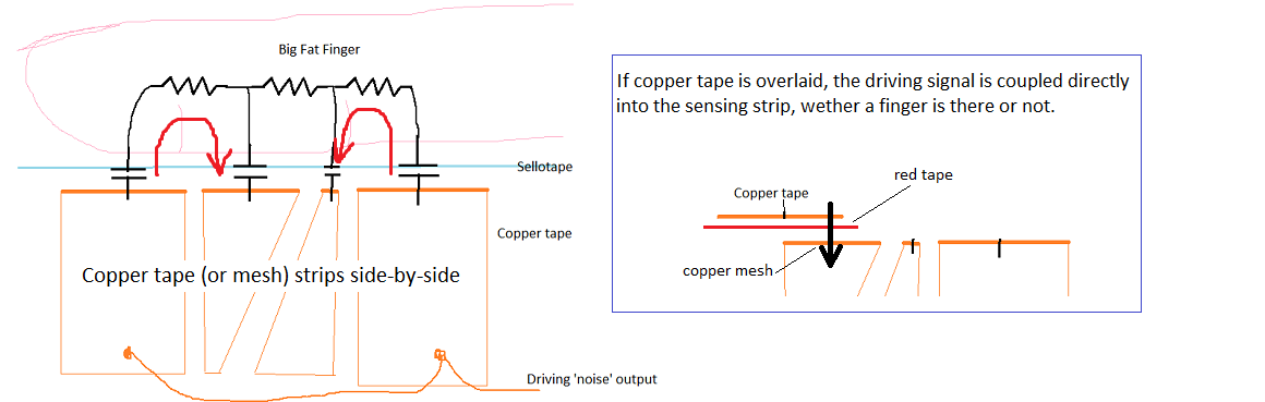
Picture3 - that's some tape on top of red tape on the mesh pole. Probably not good - the tape will make a big capacitor and mess up the sensor I think.
Picture4 - detail of the mesh and the thin end of one of the strips - ok.
Picture5 - the other end of the mesh pole? - ok
Picture6 - I'm not sure what that is showing. see my diagram again below
I'm still unfortunately using the same 1MOhm resistors rather than your suggested 10MOhms
They should be 1 MOhm, not 10 MOhms, see diagram: (it will not work without these resistors)
Progress...
Referring to some earlier comments/suggestions:
"pre-selecting the analog channel and driving the pin" like this:
digitalWrite( DRIVE_PIN, LOW );
digitalWrite( DRIVE_PIN, HIGH );
analogRead( STRIP_PIN1 );
digitalWrite( DRIVE_PIN, LOW );
digitalWrite( DRIVE_PIN, HIGH );
a0+= analogRead( STRIP_PIN1 );
...makes no difference at all.
Using fast PWM is useless... the analogRead is not synchronised to the PWM output and, as you can see from the 'scope trace below, the analog line is pulled LOW by the drive signal
Note the 'scope trace... it is essential to start an analogRead immediately after switching the drive line HIGH
you cannot read both sense strips at the same time (the input will have decayed by the time the second ADC starts)
'Scope picture (20uS/div, top trace 1V/div = analog input, bottom trace 2V/div = drive signal)

New Code
Messed with the code quite a bit and added some more calibration (now stored in EEPROM).
As well as removing the 'ambient' levels read on the analog inputs, the ratio of the signals from the strips does not go from 0% up to 100% so there's a couple more calibration steps so we can work out the low and high percentage and then scale (using map() ) the actual reading into a nice 0 to 100 range.
To use it you'll have to wire your sensor as per the above diagram (note that A0 should be connected to the "low end" wide strip) and add a button on digital pin 2.
With Serial Monitor running, press the button and it will start the calibration sequence (the onboard LED will blink showing the stage of calibration in case you have to do it without the monitor).
Keep your hand off the sensor and press the button again.
Put your hand on the low end, press the button
Put your hand on the high end and press the button.
It should then be running and calibrated. (the values are stored in EEPROM, so it will start with these values next time).
Exactly how you hold the sensor is quite important
I found the most accurate to be having you palm on the back of the pole and your 4 fingers wrapping over both sense strips. (the least accurate is putting your palm on the strips - because you tend to cover more of one strip than the other).
Code was too big to include inline... attached.
Yours,
TonyWilk
CapStrip2.ino (9.52 KB)