I've just bought the following photodiode (here) and I am trying to make a simple Arduino circuit/code so that the photodiode when placed on the screen it would be able to capture the frequency of a preset flickering object.
The flickering object is just a simple code of a white rectangle to be drawn on the screen that goes on and off at certain frequency (e.g. 30 Hz --> 1/30 = 0.033 sec/cycle).
I would like some help as my knowledge in signal processing is minimal, and I would appreciate any feedback or tips on whether what I am doing is correct or not.
Here is the Arduino code:
#include <TimerOne.h>
#include <Arduino.h>

const float alpha = 0.6; // Filter coefficient (adjust for smoothing)
int sensorValue = 0;
float filteredValue = 0.0;


const int btnPin = 8;

const int sensorPin = A0;  // sensor pin
int sValue = 0;                 // sensor reading

void setup() {
  Serial.begin(9600);
}


void waitForButton(int btnPin){
  while(digitalRead(btnPin) != 1){
    continue;
    }
  Serial.println("Button has been pressed!");
}

void loop() {  // code that loops forever


  Serial.println("Press the button for data capturing [waiting...]");
  waitForButton(btnPin);


  double uSec = 1000000, t=0.0; // Microseconds (= 1 sec)
  auto currentTime = micros();
  auto prevTime = currentTime;
  int NoSamples = 0;

  while(t < uSec){
    currentTime = micros();
    t = (double)(currentTime - prevTime);
    // Read sensor value
    sensorValue = analogRead(sensorPin);

    // Simple moving average filter
    filteredValue = alpha * sensorValue + (1.0 - alpha) * filteredValue;

    NoSamples++;
    // Send filtered data
    Serial.println(filteredValue);


  }
  //Serial. println("No Samples: ");
  //Serial. println(NoSamples);

}
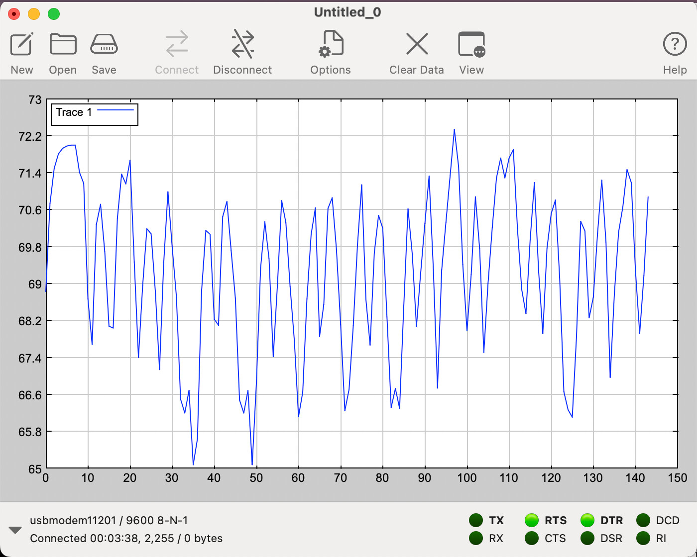
and here is the type of output I get when I read the output of a 40 Hz flickering white box on a 60 Hz monitor for 1 complete second, which looks to me still messy and not accurate actually!
1- is the photodiode code and filtering the signal correct and should give me a correct reading when exposed to a flickering signal at certain refresh rate, or must I use some specific libraries to do so (if yes, then which?)
2- do you have any suggestion for an accurate flickering stimulus that I can use as a baseline, for I suspect that the flickering process I am generating using Python/Psychopy library is not very accurate as I can see the flickering lingerring sometimes. Would an LED attached to Arduino and flickering at certain Hz (up to 100) do that or do I need another alternative?
@tatowizo
Forget about using a monitor for now and use an LED with an Arduino as you have suggested.
You will need to sample the signal at a rate of at least 10 times greater than the blinking rate.
So for 100Hz, sample the signal at 1000Hz or once every 1ms (1000us).
Don’t filter the data and see how it looks when you plot
could you please provide me with some links or hints where to read or what to do? I am at a complete loss.
is controlling the sampling rate should be done using ADC?
// Jim-p

int data_in[1000];
void setup()
{
  Serial.begin(9600);
}

void loop()
{
  int i;
  // Read 1000 data points at a sample rate of 1ms
  for (i=0;i<1000;i++)
  {
    // Read the sensor signal
    data_in[i] = analogRead(A0);
    // Wait 1000 useconds (1ms)
    delayMicroseconds(1000);
  }

  // Plot the data

}
oh just a simple for loop! I thought there was some variables need to be set to a specific sampling rate. Sorry!
I think if I need to use the photodiode and a blinking LED I would need two seperate boards operating each of the tasks as they cannot run simultanously in the same loop(), right?
Well, yes and no.
The easiest way would be to use two boards, otherwise we will have to get into using timers and interrupts.
However, there may be a simple way with one board but you will need to do some experimenting.
This code is a little crude for doing DSP but will work for testing your idea
Right now it uses the LED_BUILTIN so you can see it working, but change that to whatever pin number you use for the LED.
// Jim-p
int data_in[1000];
const byte LED_pin = LED_BUILTIN;

void setup()
{
  pinMode(LED_pin, OUTPUT); // LED output
  Serial.begin(9600);
}

void loop()
{
  int i, count=0;
  byte LED_state = 1;
  digitalWrite(LED_pin, LED_state); // LED ON

  // Read 1000 data points at a sample rate of 1ms
  for (i=0;i<1000;i++)
  {
    // Read the sensor signal
    data_in[i] = analogRead(A0);
    // Wait 1000 useconds (1ms)
    delayMicroseconds(1000);
    count++;
    // This will blink the LED at 25Hz (20ms ON, 20ms OFF)
    // but will slow down the sample rate by ~5us
    if (count == 20) // 20ms
    {
      LED_state = !LED_state;
      digitalWrite(LED_pin, LED_state);
      count = 0;
    }

  }
  digitalWrite(LED_pin, 0); // LED OFF

  // Plot the data

  delay (1000);
}
@jim-p
thanks for taking the time to answer and write the code.
I was looking around and I found that I have a Raspberry Pi, so I made use of it and configured it so to use it for the blinker LED!
Now I have the LED driven by the Rasspberry Pi at a preconfigured frequency, for now 10 Hz (just to get things right first).
and here is the output of the sensor recording with no processing or anything, does it make sense to you?
PS: oh by the way I couldn't allocate an array of size 1000 on my Arduino, it runs out of space! so I allocated 600 for now --> hence I used a delay of 1666 msec instead so to fill 600 samples.
Ah yes, since I did not include the serial.println, my code compilied OK but you are right 1000 is too big
Don't change the sample rate.
Only change the array size to 600 and the i<1000 in the for loop to i<600
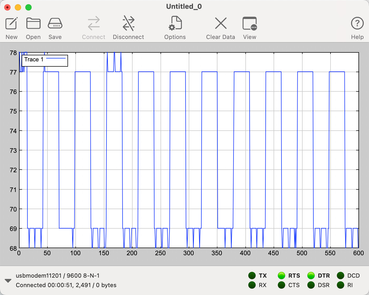
here is the kind of output right now. One can see 28 peaks for a 50 Hz signal.
I still do not understand how I am supposed to make it accurate to give an output of exactly 50 Hz (matching the LED frequency).
I am sorry but I do not seem to understand how this FreqMeasure library works and how I am supposed to integrate it in my code. Could you please clarify a bit?