I don’t have any code at the moment and the wiring is tangled and I do not have any pictures at the moment. I will provide them soon if needed though. I do have a quick mark up of a diagram of the circuit. It turns on when the power supply is plugged in. I just need it to turn off when no motion is detected.

Thanks for the schematic. Tangled wires lead to interference and unpredictable behaviour. You must have some code. If you want someone to write it for you there is a paid section of this forum. Otherwise we expect you to make an attempt and then post that attempt (in code tags) with a description of what it does and how this varies from what you want it to do. Then you can ask specific questions about it. Currently it just sounds like you are asking someone else to do the whole project for you.
Did you look at the example schematics kindly provided for you by LarryD?
Thanks for posting the diagram. Just want to be sure that the mosfet source is connected to both 12V and Arduino GND
It’s not. Should I connect it to that though?

What is the part number of the transistor ?
If this is an N channel MOSFET, the Arduino GND needs to be common to the 12V GND.
It is an IRF740 MOSFET
Good point by LarryD about being certain about the type of mosfet.
Yes, your N-channel mosfet source and the Arduino ground need to be connected.
It is not a logic level mosfet. According to the data sheet, they quote Rds(ON) at 10 V. I would suggest choosing from one of the logic level ones in the diagram in post 8
That’s odd. In the buying description it said it was logic level. Is there any way I can make use of this one? When I plug it into the power supply it does turn on the LEDs and when the wire from the MOSFET to the arduino is touched, it changes brightness.
With a volt meter, check the voltage across the Drain to Source when the LED strip is turned on.
What do you measure ?
Is that the same as a multimeter? I have one of those
Yes, use the voltage range.
I’ve set it on DCV20 there’s a few other settings though
First try the 20V range, let’s say you see .5 volts.
Then go to the 2V range, let’s say you now see .532 volts.
What do you actually see ?
On DCV20 it fluctuated but went up to about 1.01
On DCV200 it went to 0.5
It appears the MOSFET is turning on fully if the Vds = 1V
However, a Logic Level MOSFET would probably have less than .05V.
Therefore you can safely use the MOSFET.
Thank you. Does this mean I can run the 12v with the arduino, no problem. Also, I’m a bit confused why it changes the brightness when I touch the pin/wire of the one connected from the MOSFET to arduino. Thanks once again, I’ll work on the gnd etc. and send in the code I have so far.
The Arduino GND (0v) must be connected to the 12v GND.
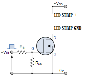
Vdd is your +12v
Make Rin = 220 Ω
Make Rgs = 10k
This topic was automatically closed 180 days after the last reply. New replies are no longer allowed.