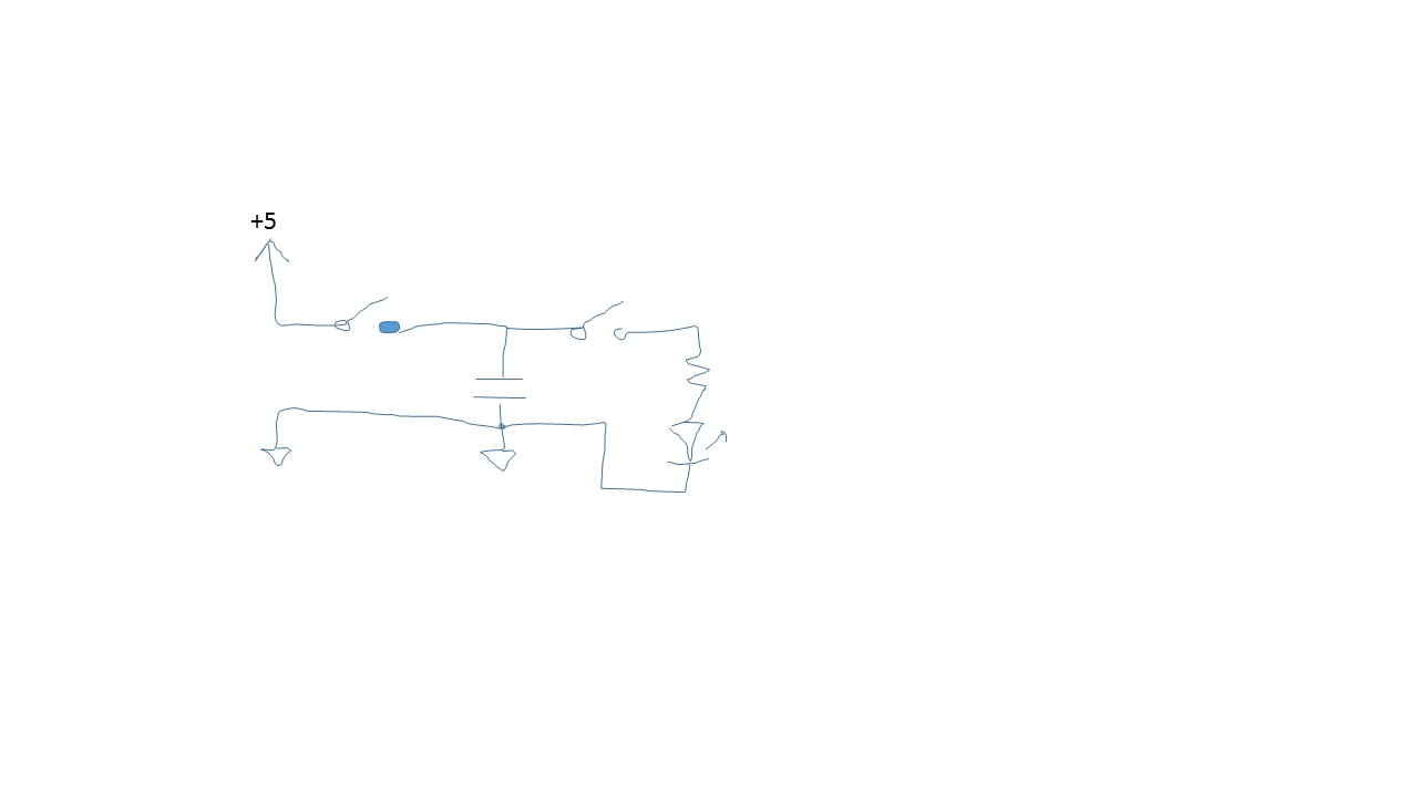
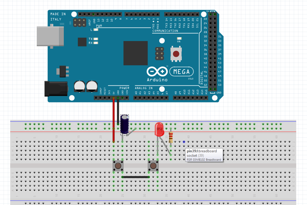
im doing a simple charge and discharge project with a 330v/160uF cap with a standard 5v usb power source on the mega.
when i set this up on my board it it charges the capacitor and when i press the second button the discharge the cap to light up the light for a second it doesnt do anything. i checked the cap and the light and its working.
Put a current limit in series with the LED, 270 or 330 ohm.
Make sure the LED is not installed backwards.
Connect the cap- to Gnd, and the 2nd button to the cap +.
You're going to have a hard time with engineering as a career then.
Two buttons, a cap, a resistor, an LED, power, Gnd. That's a pretty simple schematic.
In that fritzing diagram I see no connections to ground anywhere except to the power rail, unless you made a mistake in the diagram, which would explain why it's not working.
The one in post #10 shows the ground attached to the topmost rail. Nothing else is connected to that rail...
Crossroads: The pin he shows as connected to the cap is electrically connected to the wire between the two switches - those switches have two pins connected to each side of the switch.
Which is another thing to look at - make sure the switches are the right way around
Turns out..it was the damn breadboard that was giving out. I redid the entire schematic on a different breadboard and bam it worked the first try. i did it right i was able to press button 1 and hold it to charge it then second button to release the charge to run the led.
i even went as far as add more capacitors in parallel to extend the led light by a good 2.8 seconds. so now i got a mini capacitor bank.
so my next step is to put then in series and dump them and have my clamps observe the voltage spike.