Without knowing how much power those LED bulbs take, can't say whether your USB supply can handle this.
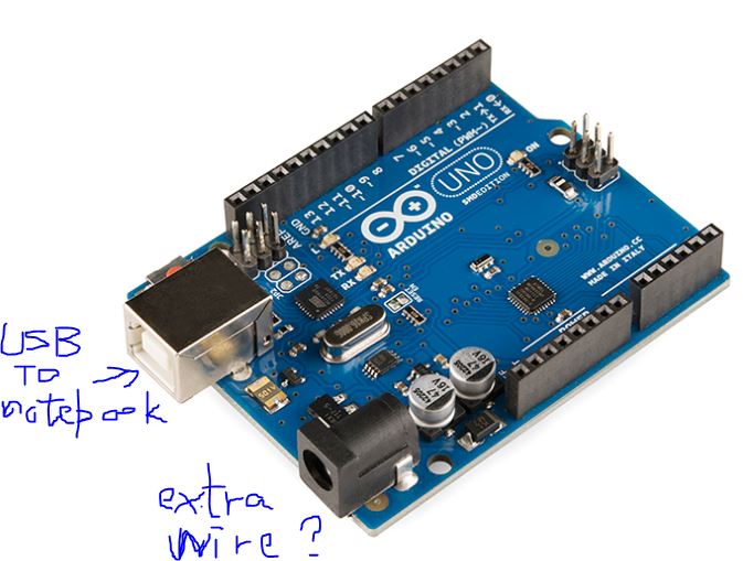
Do note that your Arduino pins can source no more than 20 mA, and just by counting the LEDs in that bulb I'm quite sure you'll be drawing more than that - so you need a hardware driver (transistor or MOSFET). Also not sure if it's a good idea take this power through the Arduino, maybe safer to have a power wire from your USB bypassing the Arduino.
wvmarle:
Without knowing how much power those LED bulbs take, can't say whether your USB supply can handle this.
Do note that your Arduino pins can source no more than 20 mA, and just by counting the LEDs in that bulb I'm quite sure you'll be drawing more than that - so you need a hardware driver (transistor or MOSFET). Also not sure if it's a good idea take this power through the Arduino, maybe safer to have a power wire from your USB bypassing the Arduino.
Thanks for your reply!
It claims that it has 5V for the LED bulbs. <-- can it be calculating the power supply?
What is the "power wire from your USB bypassing the Arduino."?
qkqk01qk:
What is the "power wire from your USB bypassing the Arduino."?
Extra wire from USB power for your lights. Not through the Arduino.
qkqk01qk:
Does any other sensor that can sense an object like a small ball?
E.g. break beam sensor, pressure sensor, piezo sensor. A piezo is actually a kind of pressure sensor and may be more suitable for measuring short impact like a ball bouncing off of it.
Which is true, but, the current is important. An Arduino pin can only supply 20mA.
The picture you posted in reply #3 is a totally different thing than the picture in the original post. They are not the same thing and they get driven in different ways.
In reply #3 you have an array of 8 WS2812b LEDs. These deed to be driven with a single data pin with the appropriate libiary. These are variable colour lights and can have their brightness altered. Many of these can be driven by one single Arduino pin. Each unit like this will take up to 480mA. However being a cheap crappy product they have not soldered in the 0.1uF ceramic capacitors needed for each LED.
In the original post you have an array of white LEDs. If they are normal power then they will take 160mA but could take a lot more. In any case you will need a driver transistor or FET on the Arduino pin to connect them.
Sorry for that I placed a wrong image, what I want is the original LED light (attached image with front face).
As you said "this will take up 160mA", Is that meaning for each LED light will take up 160mA and so it is not enough supply for one Arduino pin that can only supply 20mA?
So what should I do to solve this problem?
I also concern about whether the Arduino pin is enough for the ten sensors and ten LED light.
Is that meaning for each LED light will take up 160mA and so it is not enough supply for one Arduino pin that can only supply 20mA?
Yes each light will take a minimum of 160mA but maybe a lot more, you can't tell from the photograph. If you could tell me the numbers on the resistors we would get a better idea, they should all be the same.
So what should I do to solve this problem?
Put a transistor & resistor between each Arduino pin and the light, like this Transistors - SparkFun Learn. Note that your LED assembly already contains the resistor.
I also concern about whether the Arduino pin is enough for the ten sensors and ten LED light.
Yes you have 20 pins on the Arduino, that is "just" enough. You might have to disconnect the things on pins 0 & 1 while you upload code, then disconnect and attach them before powering up again.
Grumpy_Mike:
Yes each light will take a minimum of 160mA but maybe a lot more, you can't tell from the photograph. If you could tell me the numbers on the resistors we would get a better idea, they should all be the same.
Put a transistor & resistor between each Arduino pin and the light, like this Transistors - SparkFun Learn. Note that your LED assembly already contains the resistor.
Yes you have 20 pins on the Arduino, that is "just" enough. You might have to disconnect the things on pins 0 & 1 while you upload code, then disconnect and attach them before powering up again.
Many thanks of your reply!
I have no concept on transistor & resistor but I will try to research it.
So after I put the transistor & resistor between each Arduino pin and the light, and also attached the ten sensors to Arduino. How can I calculate the current and choose an enough extra power supply for the Arduino. (Assume I just connected a USB cable to my notebook since I need to display the sensor data.)
How can I calculate the current and choose an enough extra power supply for the Arduino.
You measure the current draw of one lamp with your DVM by putting it into current mode and applying one end to the +5V of the lamp and the other end to the actual 5V supply. Then you multiply the current reading by 10 to get the total current you need. What are these "sensors" you haven't said. You add on 10 times the sensors current and add 50mA for the Arduino. That is the minimum rating of your 5V external supply.
If you haven't got a DVM you buy one from a thrift shop, should cost you about $10.
wvmarle:
Extra wire from USB power for your lights. Not through the Arduino.
E.g. break beam sensor, pressure sensor, piezo sensor. A piezo is actually a kind of pressure sensor and may be more suitable for measuring short impact like a ball bouncing off of it.
Is the extra wire attached in this port?
(Image attached)
Grumpy_Mike:
No.
It goes from the positive of your extra 5V power supply to the 5V input on the lamps.
The negitave of your extra 5V power supply goes to the Arduino ground.
Hello, now I want to detect a tennis ball dropped down with using 10 crash sensors.
I hope this ball can have sufficient fall power to trigger the sensor.
but I am worried about the current with using one Arduino Uno R3.
Don't worry. It has.
Hello, now I want to detect a tennis ball dropped down with using 10 crash sensors.
I don't understand how you are going to use 10 sensors. These do not register as a ball passes it but when it lands on it.
each sensor takes 3.5V-5V according to the seller
Current is NOT voltage. These sensors are just simple micro switches and should be used just like push buttons. Wire on contact to ground and the other contact to an Arduino. When writing the code set the pin mode to INPUT_PULLUP. When a ball closes the switch the pin will read as a LOW, otherwise it reads as HIGH.
The internal pull up resistors take less than 0.15mA, this is an insignificant amount of current.
What I want to make is a machine that contains 10 holes, the player will put a ball on top of the machine, then the ball will drop down and collide some obstacles, finally will drop to one of the holes.
So I want to put 10 sensors for the 10 holes to detect when the ball dropped into the hole.
After some searching on the Internet, I cannot find a sensor that can detect a ball touched with the sensor. Only I found is for detecting human finger. So I may try to use a heavier ball like tennis ball with crash sensor.
Grumpy_Mike:
The internal pull up resistors take less than 0.15mA, this is an insignificant amount of current.
So this means 0.15mA*10 sensors and enough for Arduino with USB to notebook connection?
You have various options for this. Indeed microswitch may work (triggered by the ball as it falls through the opening), or optical such as a break beam sensor that is triggered when a ball blocks its path.
So this means 0.15mA*10 sensors and enough for Arduino with USB to notebook connection?
It is a totally insignificant amount of current, stop worrying about it.
Yes the switch will register a tennis ball falling on it, but you will have to arrange that it rolls off because once one ball is on a switch the switch will not register another.
instead of ground? since I never use ground before.
and the long distance (0.5m for the farthest sensor) is not a problem for current supply?
I may consider buying direct wire (~0.5m) rather than 10cm*5 wires connect.