Hi all,
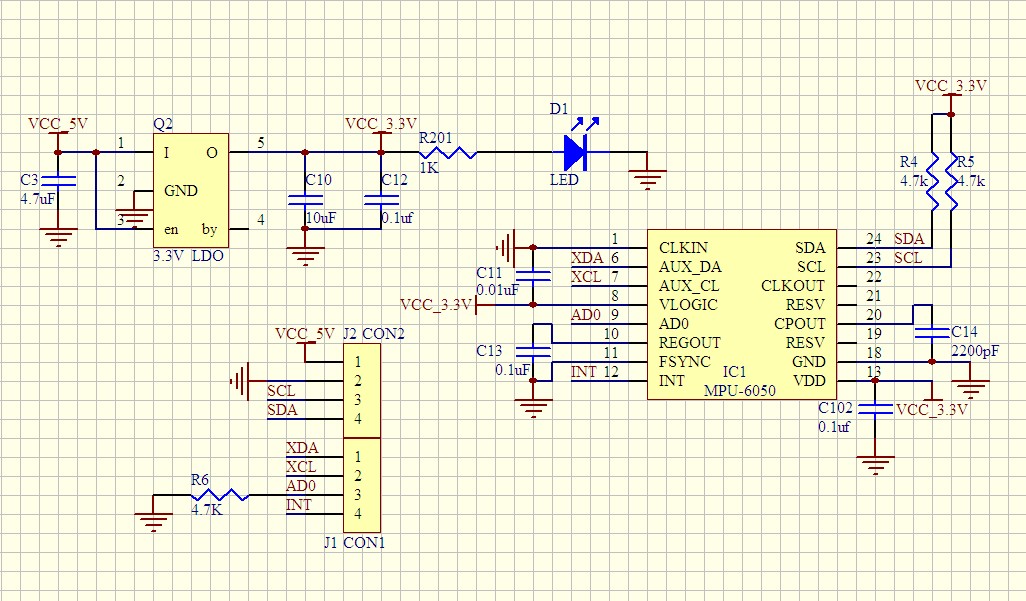
I want to connect my Arduino Mega2560 (5V) to an MPU6050 sensor (3.3V) (mounted on a GY-521 breakout board) using I2C with a logic level converter on the I2C bus. I want to ensure that the MPU6050 SDA/SCL pins do not seen any voltage higher than ~3.3V and no current greater than is specified as allowable by the datasheet. For reference my circuit diagram is as follows (although it does not show the resistors):
Circuit Diagram -
First Question
I want to find out what the maximum allowable current into the MPU6050 SDA/SCL pins is?
I have tried to read the datasheet (link) but cannot see the information stated. Following is an excerpt which I presumed would be where the information would be found, but am not 100% sure what these specs are referring to.
Datasheet Excerpt - http://i.imgur.com/fPOOM6U.png
Second Question
I also want to work out what current the SDA/SCL pins will see (when the sensor pulls SDA/SCL low) given my current pull-up resistor configuration?
On the official Arduino site page regarding logic level converters it states;
A device that pulls a line down has to handle the current through both resistors (on the 3.3V side and on the 5V side).
My pull-up resistor configuration is linked below. The 4.7k pull-up resistors to 3.3V are on the MPU6050 breakout board, the 10k pull-up resistors are on the logic level converter on both the 3.3V and 5V sides, and the 20k pull-up resistors to 5V are (as I understand it from the ATMega 2560 datasheet) internal to the microcontroller and activated by the Wire library. Note that the Mega2560 comes with on board 10k pullup resistors to 5V on both SDA/SCL but I have desoldered these.
Pull-up Resistor Configuration -
Would the current essentially be I=V/R, where R is all 4 resistors in parallel (2.16k equivalent?), and V is 3.3V (or 5V)?
Thanks in advance.
Why did you desolder the resistors? Every I2C bus should be terminated with pullup resistors at both ends. Both the 5V and 3.3V buses have to be terminated this way. You can use an ammeter to find out the current drawn in low signal state.
The data sheet says that the MPU6050 Iol should not be higher than 3mA.
The GY-521 has level translators so you can use 5V inputs.
Thanks all for the replies.
ricky101,
I'm new to Arduino/electronics so I'm finding that article a bit difficult to understand and use to answer my questions. I will keep it as reference for the moment.
DrDiettrich,
I desoldered the onboard 10k resistors on the Mega2560 so that SDA/SCL wouldn't be pulled up to 5V (before I discovered the internal pullups to 5V in the Mega2560 chip and on the logic level converter). As far as I am aware the other 5V Arduino boards don't have on board (external) pullup resistors like the Mega2560, only internal. The aim of desoldering them was so that SDA and SCL would only be pulled to 3.3V (via the 4k7 resistors on the MPU6050 breakout board) - the Mega2560 would still interpret 3.3V as a logic high. But as per my pullup configuration (see below, and linked in first post) it is still terminated to 5V in the Mega2560 and on the 5V side of the logic level converter.
Thank you for pointing out the 3mA requirement, I wasn't sure if that was the line that answered my question.
I don't want to connect the sensor to the Arduino and power it (to measure with ammeter) until I can do a quick calculation first of what current it will see on SDA/SCL lines given my pullup configuration when pulled low, because if it is higher than what is allowable it could damage the sensor. I'm not sure how to do that calculation however.
charliesixpack,
That is a voltage regulator so you can provide 5V VCC to the GY-521 breakout board and it will step it down to 3.3V as supply voltage to the sensor. It is not a logic level converter.
Edit:
I believe it may be calculated as follows, if anyone can confirm that would be great.
Rp1 = 4700 ohms (Breakout board pullup resistor)
Rp2 = 10000 ohms (Logic level converter pullup resistor on 3.3V side)
Rp3 = 10000 ohms (Logic level converter pullup resistor on 5V side)
Rp4 = 20000 ohms (Mega2560 internal pullup resistor)
I = { 3.3 / [(Rp1Rp2)/(Rp1+Rp2)] } + { 5 / [(Rp3Rp4)/(Rp3+Rp4)] }
I = 3.3 / 3197 + 5 / 6666
I = 1.03 mA + 0.75 mA
I = 1.78 mA ?