Hi guys!
I am new to arduino programming, so i got stuck on this issue.
I am generating a PWM using arduino uno timer 1 (different frequencies between 19Hz to 26Hz). I need to turn this PWM off in different time durations (like 0.5 seconds). This is where i am using timer 2.
PWM generation without timer 2 is ok. but when i turn timer 2 on, the output isn't what i want.
The PWM turns on (after i send 1 from the serial port), if i want to turn the PWM off after 2 seconds, it instead starts sending weird signals at around 2.7 seconds. if i send another 1 from the serial port, the PWM turns on again, and turns off correctly the second time (but again after 2.7 second).
i used the formula
F=freq clk/(2 . pre scal . (1 + OCRn))
and OCRn was 77
allowing me to have 0.5 seconds delay in every 50 cycles.
Before i used timer 2, i tried to use delay() function, but it also kinda gave the same results, but not every time.
Any idea what might be happening here? why it doesn't work the first time but works the second time? and is there something wrong with my calculation for timer 2?
DrDiettrich:
I'd update the control registers only once, not in multiple steps as you do for e.g. TCCR2B.
I changed the using instead
TCCR2B=0x07
and TCCR1B=0x0C
however the problem is still there
I see a warning in this new version of Ardiuno Software IDE
sketch_nov10a.ino:100:13: warning: character constant too long for its type [enabled by default]


        case 'default':

             ^

sketch_nov10a.ino: In function 'void loop()':

sketch_nov10a.ino:100:13: warning: case label value exceeds maximum value for type [enabled by default]
Your switch case syntax is incorrect. Take the single quotes from 'default' and put it at the end.
switch (var) {
    case 1:
      //do something when var equals 1
      break;
    case 2:
      //do something when var equals 2
      break;
    default:
      // if nothing else matches, do the default
      // default is optional
    break;
  }
Please post your entire code, with set up, variable declarations, etc.. What you post should compile and run so that we can test and debug it.
PWM generation without timer 2 is ok. but when i turn timer 2 on, the output isn't what i want.
The PWM turns on (after i send 1 from the serial port), if i want to turn the PWM off after 2 seconds, it instead starts sending weird signals at around 2.7 seconds. if i send another 1 from the serial port, the PWM turns on again, and turns off correctly the second time (but again after 2.7 second).
How are you determining what is happening with Timer2?
I have modified your code to put in some time stamps through the process, and I've added a small delay to better see what is happening. I can not repeat your erratic output or your timing problem. Timer2 turns on the pin13 led for one second when a '1" is entered in the serial monitor.
What frequency processor does your Arduino have? Your timer1 looks set up for 16Mhz.
But, timer2 was set up for 8Mhz with prescaler 1024 and OCR2A = 77 and 200 matches.
I have modified your timer2 setup for 16mz with a prescaler of 128, OCR2A= 124 for a 1 ms ctc, and 2000
counts for the two seconds.
Your code can be tightened up in several ways, but for now, I'd like to get a better understanding of the main problem.
cattledog:
How are you determining what is happening with Timer2?
I have modified your code to put in some time stamps through the process, and I've added a small delay to better see what is happening. I can not repeat your erratic output or your timing problem. Timer2 turns on the pin13 led for one second when a '1" is entered in the serial monitor.
What frequency processor does your Arduino have? Your timer1 looks set up for 16Mhz.
But, timer2 was set up for 8Mhz with prescaler 1024 and OCR2A = 77 and 200 matches.
I have modified your timer2 setup for 16mz with a prescaler of 128, OCR2A= 124 for a 1 ms ctc, and 2000
counts for the two seconds.
Your code can be tightened up in several ways, but for now, I'd like to get a better understanding of the main problem.
I had an oscilloscope in my lab. and i used a stop watch.
I am using Arduino Uno. the is Atmega328P, i was told that it 16Mhz clock, though default is 8MHz in the data sheet.
yeah, all my timers were supposed to be set for 16MHz. I wasn't aware i was using 8MHz somehow for timer 2.
i used the formula
F=freq clk/(2 . pre scal . (1 + OCRn))
and i put 16Mhz for the clk. How did i set it for 8Mhz?
But thanks for fixing timer2. now it giving the right delay.
I used the LED as a signal for when the PWM is on.
I am driving vibrating motors 'coin permanent-magnetic motors DC model C1026B series' with this PWM.
it will run fine if timer 2 isn't there. but once i add it. it gives me this eratic result. even now
the LED turns off at the approiate time but the vibration becomes very eratic (first 1 i send). the second 1 i sent works ok.
(all the odd 1s don't work and the even 1s work for the PWM)
does this information helps?
Before using timer2, i also tried to use simple delays
but they also sometime worked and sometimes didn't, but they weren't as consistent as this.
i used the formula
F=freq clk/(2 . pre scal . (1 + OCRn))
and i put 16Mhz for the clk. How did i set it for 8Mhz?
You used that formula to set up timer1 for the 26HZ square wave, and not timer2 for the enabled period.
I'm not sure I understand the oscilloscope traces, but from image 1 and image 5 it looks like you are showing the 26Hz square wave with some sort of ripple on the top.
it gives me this eratic result. even now
the LED turns off at the approiate time but the vibration becomes very eratic (first 1 i send). the second 1 i sent works ok.
(all the odd 1s don't work and the even 1s work for the PWM)
I can not confirm this.
I don't have a scope, and obviously I can not debug with your motors and actual setup, but if I add an external interrupt to the sketch to monitor the timer1 output ((jumper pin D10 to pin D2) I can count 26 pulses each second during the two second enabled period. It happens every time I enter a "1" in the monitor. There is no even/ON and odd?OFF behaviour. Here's the program I am running to test your sketch.
I don't know what the problem is. But your code to disable the timer 1 interrupt is incorrect. I don't think it matters in this case because you're shutting down the timer. But you should fix it just the same. This line is essentially a NOP:
I don't know what the problem is. But your code to disable the timer 1 interrupt is incorrect. I don't think it matters in this case because you're shutting down the timer. But you should fix it just the same. This line is essentially a NOP:
It's also worth pointing out that you're not doing pulse width modulation. You're generating a square wave.
If you could use either digital pin 9 or 10 you could eliminate the timer 1 ISR and let the hardware toggle the pin for you.
Yes, there is some incorrect syntax with TIMSK1, and the approach to timer management can be tightened up. Some configuration can be moved to setup, and I'd prefer to disable the timers by just writing 000 into the CS/prescaler bits but I don't think these issues are relevant to what the OP is seeing. I've tried his sketch with some simplified timer handling, but it didn't change what I was seeing.
cattledog:
You used that formula to set up timer1 for the 26HZ square wave, and not timer2 for the enabled period.
I'm not sure I understand the oscilloscope traces, but from image 1 and image 5 it looks like you are showing the 26Hz square wave with some sort of ripple on the top.
I can not confirm this.
I don't have a scope, and obviously I can not debug with your motors and actual setup, but if I add an external interrupt to the sketch to monitor the timer1 output ((jumper pin D10 to pin D2) I can count 26 pulses each second during the two second enabled period. It happens every time I enter a "1" in the monitor. There is no even/ON and odd?OFF behaviour. Here's the program I am running to test your sketch.
Those square waves works fine for my requirements.
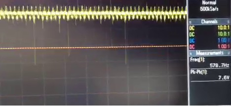
the last image shows the square wave shut down. note the mV on the side of the scope.
the images number 2 to 4 shows the wrong output, when the square waves doesn't shut down correctly, note different frequencies in the images and voltage form 7V to 10.9V. This drives my motor crazy.
You don't see the pulses after sending 1 (two seconds later), because there are non, but still some sort of output (images 2 to 4).
i will remove the TIMSK1 thing and do the prescale bits instead
jboyton:
I don't know what the problem is. But your code to disable the timer 1 interrupt is incorrect. I don't think it matters in this case because you're shutting down the timer. But you should fix it just the same. This line is essentially a NOP:
It's also worth pointing out that you're not doing pulse width modulation. You're generating a square wave.
If you could use either digital pin 9 or 10 you could eliminate the timer 1 ISR and let the hardware toggle the pin for you.
I removed the line.
but the problem is still there, maybe if i used the hardware toggle the problem might go away. because the output doesn't turn off correctly.
What do i change to use PWM mode instead.
I can confirm the odd/even shut off behavior you see in code when I added some digitalReads of pin 10 into the test code. It is due to the fact that because of the toggle, RightPin 10 can be left either HIGH or LOW at the end of the Timer1 ISR.
ISR(TIMER1_COMPA_vect)          // timer compare interrupt service routine
{
  digitalWrite(RightPin, digitalRead(RightPin) ^ 1);   // toggle LED pin
}
To fix this, In the ISR for Timer 2, you need to set the RightPin LOW at the end of the timed sequence.
cattledog:
I can confirm the odd/even shut off behavior you see in code when I added some digitalReads of pin 10 into the test code. It is due to the fact that because of the toggle, RightPin 10 can be left either HIGH or LOW at the end of the Timer1 ISR.
//*****************************************
digitalWrite(RightPin,LOW);// add this line
//*****************************************
I feel really stupid right now . In my defense, i showed couple of other people who actually new arduino programming, and they didn't see it either.
Thanks alot. the code is working perfectly now. though i don't know if the 0.5 second delay is accurate or not. the 1 second and 1.5 second delay looks ok. can you confirm the delays are accurate, i don't know how to read the serial monitor, especially when it scrolls it self so fast.
cattledog:
As a matter of interest, where is the 12v coming from? I thought the coin motors were 3v. What is connected to pin 10 of the Arduino?
I really didn't think about it too much that why i didn't try forcing the output low.
you are right, the voltage is coming from the controller (3.3V). Pin 10 is connected to 1k ohm resister and then a transistor.
3.3V is directly connected to the motor and the other end is connected to the transistor.
Th oscilloscope was connected before the transistor, to the resistor instead.
Thanks alot. the code is working perfectly now. though i don't know if the 0.5 second delay is accurate or not. the 1 second and 1.5 second delay looks ok. can you confirm the delays are accurate
All the enabled periods from .5 to 2.0 seconds look correct to me with my testing.
I think your OCR1A calculation is off by 1. Check the datasheet to be sure, but I believe you need to subtract one. It's a small error (0.01%) so you wouldn't likely notice it. EDIT: My bad, I forgot to round the result.
Since you're using pin 10 you can delete your ISR(TIMER1_COMPA_vect) function and use the hardware to toggle the pin automatically. Try these functions. The first one starts the square wave and the second one shuts it off. I use this approach in my current project. The square wave runs while the processor sleeps in idle mode. No need to service any interrupts.
// ---------------------------------------------------------------------------------------
// startSQW - turns on square wave (OC1B, digital pin 10)
// ---------------------------------------------------------------------------------------
void startSQW()
{
  int frequency = 26;
  int prescaler = 256;

  TCCR1A = bit(COM1B0);                      // toggle OC1B on compare match
  TCCR1B = bit(WGM12) | bit(CS12);           // CTC mode, prescaler = 256
  OCR1A = (((F_CPU/prescaler)/frequency)+1)/2 - 1;
}

// ---------------------------------------------------------------------------------------
// stopSQW - turns off square wave
// ---------------------------------------------------------------------------------------
void stopSQW()
{
  TCCR1B = 0;                                // stop timer
  TCCR1A = bit(COM1B1);                      // clear OC1B on compare match
  TCCR1C = bit(FOC1B);                       // force compare to set OC1B low
}