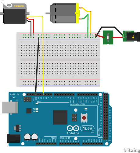
I'm getting ready to assemble a prototype piece of my project, and I just want to check that I have the correct breadboard wiring based on my schematic, and that I'm not missing any important component or connection? (DC motor is only supposed to be controlled by the switch. Servo motor is controlled by the Arduino.) Thanks.
The schematic shows you using D11 and the breadboard uses D12
Your motor will run when ever you have the switch closed, is this what you want?
I use the Red marked rail as the positive and the Blue marked rail as neg.
There may be noise from the motor feed back to the controller.
LarryD:
The schematic shows you using D11 and the breadboard uses D12
Your motor will run when ever you have the switch closed, is this what you want?I use the Red marked rail as the positive and the Blue marked rail as neg.
There may be noise from the motor feed back to the controller.
Whoops. Thanks for pointing that out (I also switched the +/- below because that makes sense). And yes, I want the dc motor to run as long as I have the switch closed. What would be your suggestion to reduce or eliminate noise from motor feedback (the servo, I assume)? Thanks for your help.
The red and blue as + and - is just a convention I use, just a suggestion.
For noise suppression, I place a diode across the leads (reversed biased) i.e. Anode to negative and Cathode to positive.
I use 1N4007s.
I some times add a capacitor across the same leads, 0.1 to 1uf for small hobby motors.
LarryD:
The red and blue as + and - is just a convention I use, just a suggestion.
For noise suppression, I place a diode across the leads (reversed biased) i.e. Anode to negative and Cathode to positive.
I use 1N4007s.
I some times add a capacitor across the same leads, 0.1 to 1uf for small hobby motors.
You mean a flyback diode, right? If so, do you mean add it to the servo, or the dc, or both? And would a 1N4001 be fine (the only one I can find on adafruit)? Thanks.
Since the motors are wired in parallel place one diode, 1N4001 is fine.
You should get in the habit of using a diode across DC coil devices as there are inductive transients generated by them, it costs very little.
LarryD:
Since the motors are wired in parallel place one diode, 1N4001 is fine.
You should get in the habit of using a diode across DC coil devices as there are inductive transients generated by them, it costs very little.
I see. Thank you!
I have a question about adafruit's barrel jack (http://www.adafruit.com/datasheets/21mmdcjackDatasheet.pdf). I know that I need to watch the polarity of the servo, so the positive wire (red?) connects to pin 1, and the negative/ground wire (black?) connects to pin 2 (leaving pin 3 floating)? Thanks.
Confirm your wall wart uses the center as the positive.
LarryD:
Confirm your wall wart uses the center as the positive.
Do I check that with my multimeter? I bought adafruit's 5v 10a adapter (5V 10A switching power supply : ID 658 : Adafruit Industries, Unique & fun DIY electronics and kits), but I can't find any datasheet on it (I got a high current adapter for when I'm ready to add more motors to my circuit).
Do I check that with my multimeter?
Yes.


