hi
I am using a rotary encoder when I turn it to one direction the counting is correct but when I turn the encoder shaft to the other direction the counting values won't be decreased and it would be increased!
this is my code:
#include <Encoder.h>
Encoder myEncoder(2,3);
double Position;

void setup() {
  Serial.begin(250000);
  Serial.println("DC POSITION.");

}
long oldPosition = -999;
void loop() {
  long newPosition = myEncoder.read();
  if (newPosition != oldPosition) {
    oldPosition = newPosition ;
  }

Serial.print("Position = ");
Serial.println(newPosition);


}
I am using a rotary encoder
Can you please provide more specific information about the encoder you are using.
You probably connected it wrong. My guess is that you connected either the A or B pin to ground instead of the common pin.
Check with the datasheet of your specific encoder, or check the markings on the enclosure. If you can't find the correct pinout, just swap the pins and try all possible combinations until it works correctly.
Pieter
this is the datasheet of the encoder and I'm sure about correct wiring
E40.pdf (634 KB)
I'm sure about correct wiring
Do you know the specific part number of your encoder. There are multiple output configurations, and the connections to the Arduino with pull ups or pull downs will vary.
You are using library example code, so I'm less certain than you are about the correct wiring.
How about a wiring diagram? even a hand drawn one scanned would work
the color of the wires :
blue 12~24 V
brown 0 V
black A
white B
orange Z
so I connected the blue wire to the + of a 12V power supply and the brown one to the - of the power supply also I connected the black wire to the pin2 of Arduino board and white one to the pin3.
Did you connect the ground of the Arduino to the 0V of the encoder?
koronus:
the color of the wires :
blue 12~24 V
brown 0 V
black A
white B
orange Z
so I connected the blue wire to the + of a 12V power supply and the brown one to the - of the power supply also I connected the black wire to the pin2 of Arduino board and white one to the pin3.
Well brown is V+ and blue is 0V, so that's wrong to start with.
Also if you have the totem-pole output 12V version its not compatible with 5V Arduino, only open collector
version at that voltage is safe.
PieterP:
Did you connect the ground of the Arduino to the 0V of the encoder?
No, I didn't
MarkT:
Well brown is V+ and blue is 0V, so that's wrong to start with.
Also if you have the totem-pole output 12V version its not compatible with 5V Arduino, only open collector
version at that voltage is safe.
Do you mean that this encoder won't match with 5V Arduino?
Do you mean that this encoder won't match with 5V Arduino?
It appears that you have a 12-24 v model of the encoder. We still don't know the exact part number of the encoder to know what type of output it supplies. How may wires are coming from the encoder? If the output is open collector, then you can use a 5v pullup.
If the output is not open collector, and you haven't already destroyed your Arduino by connecting inputs to 12v, the output can probably be passed through some sort of voltage divider to work.
this is the datasheet which had been sent with the encoder:
and it is a totem pole!
Hi,
What is the exact part number of your encoder, please?
Can you please post a copy of your circuit, in CAD or a picture of a hand drawn circuit in jpg, png?
Thanks.. Tom... 
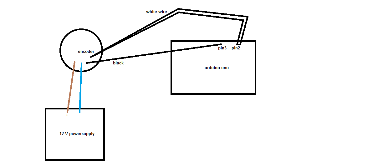
-
You must connect the grounds.
-
You must not connect 12V to an Arduino input.
What is the exact part number you have? There's a lot of options on that datasheet.
this is the datasheet which had been sent with the encoder and it is a totem pole!
With a 12v power supply, your totem pole(push-pull) A/B outputs are going to 12V HIGH and 0V low. You can use a voltage divider or an optocoupler on the outputs to get them to 5v for the Arduino.
If you use a voltage divider to ground there are two factors to consider. I looks like the max current output is 10ma, so that means at 12V your resistance network will need to be at least 1200 ohms total. You will also need to have a connection point at which divided 12v is greater than 3.0v in order for the Arduino to read it as HIGH. The closer you can get it to 5V the better. What you do will depend on the resistors available to you.
Here's a link to a voltage divider calculator. You will see that 1K/470 should work with 3.8v out.
An alternative to the voltage divider is to use an optocoupler IC. The 12v outputs will go through one side, and the other side will connect the arduino interrupt pin(using INPUT_PULLUP) to ground,
You will also need to connect the Grounds between the 12v encoder and the 5v Arduino.
MorganS:
You must connect the grounds.
You must not connect 12V to an Arduino input.
What is the exact part number you have? There's a lot of options on that datasheet.
my encoder model is:
E40S6-1000-3-T-24
