I apologize if the question is not asked that branch! Need help! I want to collect the following construction: PROCESSING takes some information from the virtual midi port and sends it to the serialport
//Import libraries
import processing.serial.*;
import promidi.*;

Serial myPort;
MidiIO midiIO;
//Message to be sent
int message=0;

void setup() {
  myPort = new Serial(this, "COM4", 9600);
  midiIO = MidiIO.getInstance(this);
  //Line that prints I/O devices in console
  midiIO.printDevices();
  //Receive input from Virtual MIDI Ports
  midiIO.openInput(0,0);
}

void draw() {}
void noteOn(Note note, int deviceNum, int midiChan){
  int vel = note.getVelocity();
  int pitch = note.getPitch();
  if(vel>0){ // If velocity > 0 set message value to note's pitch
  if(pitch==60){ message=1; } else
  if(pitch==62){ message=2; } else
  if(pitch==64){ message=3; } else
  if(pitch==65){ message=4; } else
  if(pitch==67){ message=5; } else message=0;
    } else { message=0;}
  //Send message to Arduino
  myPort.write(message);
}
arduino with a radio module NRF24I01 + on board connected to the PC listens serialport receives data {message = 1; } {Message = 2; } {Message = 3; } .... And sends them to the next with the same arduino konstrutsiey. It receives the data and performs an action (on / off LED).
Now the question is if you do not use the radio and raotat directly directly through serialport everything is fine has been online "PROCESSING ---- >>> ARDUINO" (code arduino):
// Data received from the serial port
int val;
//LEDs are connected to the following pins
int pins[] = {2,3,4,5,6};
void setup() {
  for(int i=0; i<5; i++){
  pinMode(pins[i], OUTPUT); // Set pins as OUTPUTs
  }
  Serial.begin(9600); // Start serial communication at 9600 bps
}
void loop() {
if (Serial.available()) { // If data is available to read,
val = Serial.read(); // read it and store it in val
// Turn on LEDs, depending on pitches received
  if (val == 1) { digitalWrite(pins[0],HIGH); } else
  if (val == 2) { digitalWrite(pins[1],HIGH); } else
  if (val == 3) { digitalWrite(pins[2],HIGH); } else
  if (val == 4) { digitalWrite(pins[3],HIGH); } else
  if (val == 5) { digitalWrite(pins[4],HIGH); } else
  if (val==0) { resetLEDs(); }
}
}
//Function that turns all the LEDs off
void resetLEDs(){
  for(int i=0; i<5; i++){
  digitalWrite(pins[i],LOW);
  }
}
Now cling NRF24I01 + get the following structure "PROCESSING - >> ---- >> ARDUINOperedaet ARDUINOprinimaet" code processing leave the same code Arduino transmitter:
#include <SPI.h>
#include "RF24.h"
RF24 radio(9, 10);
const uint64_t pipe= {
0xF0F0F0F000LL};// ?????? ??????? ?????? ? ????????
void setup(){
Serial.begin(9600);
radio.begin();
radio.setDataRate(RF24_250KBPS); // ???????? ????????
radio.setChannel(100); // ????? ?????? ?? 0 ?? 127
radio.setRetries(15,15); // ???-?? ??????? ? ????? ????? ?????????
radio.openWritingPipe(pipe); // ????????? ????? ????????
radio.startListening(); // ???????? ??????? ????
}

void loop(){
if(Serial.available()){
char data[32] = "";
byte i = 0;
while(Serial.available()){
data[i] = Serial.read(); //???????? ?????? ?? ??????.
i++;
delay(2);
}
data[i] = 0;
radio.stopListening();
radio.write(&data, 32); //? ?????????? ?? ? Arduino ?2
radio.startListening();
}
}
ARDUINO code receiver:
#include <SPI.h>
#include "RF24.h"
RF24 radio(9, 10);
//???? ???? ?????????? ??????????
int pins[] = {1,2,3,4,5,6,7,8};
const uint64_t pipe = {
0xF0F0F0F000LL};// ?????? ??????? ?????? ? ????????

void setup(){
  for(int i=0; i<8; i++){
  pinMode(pins[i], OUTPUT); // Set pins as OUTPUTs
  }
radio.begin();
radio.setDataRate(RF24_250KBPS); // ???????? ????????
radio.setChannel(100); // ????? ?????? ?? 0 ?? 127
radio.setRetries(15,15); // ???-?? ??????? ? ????? ????? ?????????
radio.openReadingPipe(1,pipe); // ????????? ???? ?? 6-?? ??????? ??????
radio.startListening(); // ???????? ??????? ????
}

void loop(){
if(radio.available()){
char data[32] = "";
radio.read(&data, 32); //
//???? ?????? ????? 1 ???????? ?????????
if (data[0] == '1') { digitalWrite(pins[0],HIGH); } else
if (data[0] == '2') { digitalWrite(pins[1],HIGH); } else
if (data[0] == '3') { digitalWrite(pins[2],HIGH); } else
if (data[0] == '4') { digitalWrite(pins[3],HIGH); } else
if (data[0] == '5') { digitalWrite(pins[4],HIGH); } else
if (data[0] == '6') { digitalWrite(pins[5],HIGH); } else
if (data[0] == '7') { digitalWrite(pins[6],HIGH); } else
if (data[0] == '8') { digitalWrite(pins[7],HIGH); } else
if (data[0] == '0') { resetLEDs(); }
}
}

void resetLEDs(){
for(int i=0; i<8; i++){
digitalWrite(pins[i],LOW);
  }
}
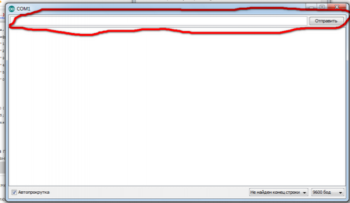
Launch and receiver silence. Only works when the data is transferred to himself through

Prompt where the error what is wrong???? possible to fix the code!
It is very necessary!
I apologize for my English!