I will check on finding the data sheet for each component. Really it is just fan and compressor. However, does it not need a duty cycle cut off. That is what I was understanding from @wildbill. So, if the humidity level never comes down; wouldn't it need to cut off and have a rest period.
Plus, Don't I need a period for the fan to run after the humidity drops to a set level and the compressor cuts off?
The only consideration I'm aware of is that short cycling a compressor is bad for it, which ties back to what @dave-in-nj was saying.
I've no idea whether the compressor has a limit on how long it can run. Thinking about HVAC, I would expect that I can run my AC all day if conditions warrant it.
My reference to rest periods came from you saying that you needed it.
However, I have continued to play with the code. I have been doing as you suggested doing it without the relays and compressor/fan connected. I haven't been using leds, but I have used serial prints to tell where I am with the code, and I think I am getting close to what I want. I have gotten it to perform what I would consider a duty cycle cut off.
Basically I have it check every hour to see how much run time has accumulated in that hour. If it is over a certain amount, it shuts off (rest period). I don't know if I need it, but I wouldn't mind having it in there. Plus I figure I am getting some practice coding.
I think I will be able to get the code to work, but it sure does look longer and more complicated than I think it should be. I have tons of if statements. I don't think this is a good thing. I am wondering if switch case would be better in this scenario, but I don't know enough about them. Guess I'll keep studying. And I will get the data sheet for the compressor.
You might be able to simplify it if you just force the compressor to run for a minimum time when it's triggered, longer if the humidity warrants it and then stay off for some specified rest time afterwards before checking humidity again.
Counting stuff in the hour sounds more complicated.
I got it going…. It’s defiantly producing water and bringing the humidity down. I can’t find any information or data sheet on the compressor. I still need to tweak code some, but now I have another concern.
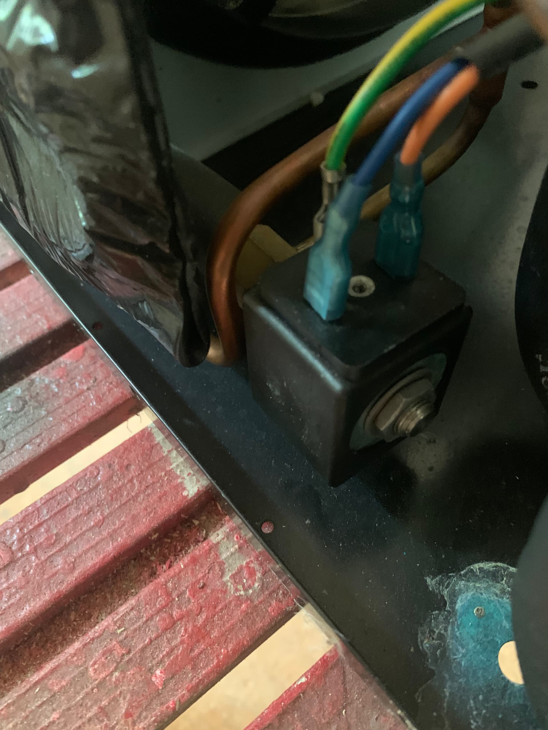
This may be the wrong place to ask this, but I’ll give it a shot. The original board had a relay that went to e.v. I think i have figured out what it is. It is the expansion valve. However, I don’t know what it does… or what tells it when to turn on and off. I thought they worked mechanically to open and close, but this one has wires that went to a relay. Any help is appreciated!
The electrics look pretty obvious. I suspect that @dave-in-nj has identified what it does, where do the copper lines go?
Given that my experience with equalizer valves goes back to oh, about 1pm, I don't know how to figure out when you should apply power to it. Maybe there's a pressure sensor somewhere. Maybe it should be activated when the compressor's running. I'm unsure how you can find out.
There are two tubes on going in to the valve/solenoid. One comes from compressor. Other goes to I what I guess would be the coils that sweat to produce the water. It is covered up with insulation and can’t tell exactly where it’s going. Here is a video to show a little more maybe:
I know the video is not very good, but the solenoid/valve is connected on one side from the discharge side of the compressor. It is not insulated and is warm to touch when running.
The other line connected to the solenoid/valve is insulated and goes toward the coil. It’s hard to tell exactly where it’s doing because it is insulated.
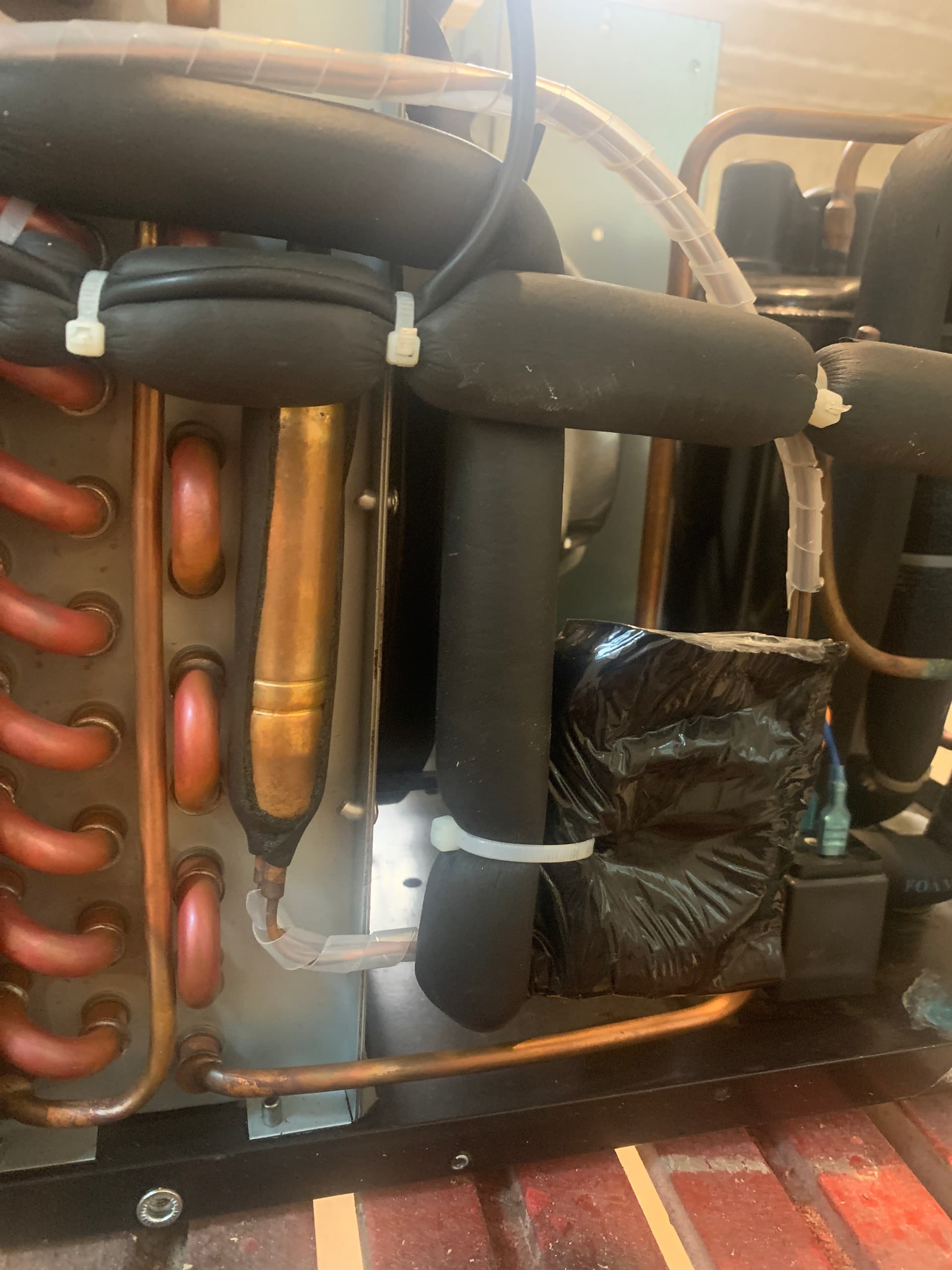
This copper cylinder thing (capillary tube?) has two small copper lines running out the bottom. And one large line coming out of the top.
The two small lines run to whatever is wrapped in insulation (black square insulation in picture and has the zip around it). And then two copper lines come out of that same black square insulated device at the top and run to the coil.
The large line at top of what I am calling capillary tube is going to the coil at the bottom. You can see where it connects at the bottom left of the picture.
Is whatever is inside of that square black insulation the expansion valve?
@dave-in-nj
I have been doing some research on pressure equalizer valves and found this:
Pressure Equalizer Valve (PEV)
At the end of every compressor operation (after the 3.5 minute
Time Guard period), the equalizer valve opens for 150 seconds
plus an additional 15 seconds of protection before allowing the
compressor to start ramping up.
The PEV is located next to the suction and discharge of the
compressor. The function of this valve is to prevent the
compressor from starting with a high refrigerant pressure
differential, thus helping the reliability of the compressor.
NOTE: A hissing sound may be heard during the equalization
process. This is normal.
This seems to be fairly simple to add. I would just need a third relay and set it up to turn on when the compressor cuts off for a certain amount of time.
Do you think a pressure equalizer valve is what I am dealing with here?
Thanks!!!!
So, if I get a third SSR (30 amp max prob over kill?) like I have for compressor and fan, and connect it to arduino. I will just have it set to energize (open?) every time the compressor turns off (stay open for 3 minutes?).
When the equalizer valve opens, this allows the compressed air time to release back in to the low pressure side of they system before the compressor kicks back on while under pressure?
Am I understanding it correctly?
@Paul_B
I have heard the sound you’re describing before, but I had no idea why it made that sound.
I think I have everything connected up and working correctly now. Since this may end up inside of a kiln for lumber, I want to be able to monitor the humidity and adjust code if necessary ota. It will be in range of a wifi ap.
I got a wemos d1 that @cattledog and others had to help me figure out how to add a basic sketch. (bad cable problems). My plan was to run the dehumidifier with this and be able to upload and review serial monitor with it. But from my understanding the serial monitor will not work this way.
My question is what is going to be the easiest way to view serial and upload code ota with the wemos and wifi?
@wildbill i know you talked about with your greenhouse project sending data to a server. This sounds complicated to me. I know nothing about servers. Is there something built in to the wemos that I can upload data to and view over wifi?
You can run a web server on the Wemos - plenty of examples on line. You can build a page that lets you change the set point and another that shows status.
It might be easier to just build the set point page and send data elsewhere to be displayed. There are a number of services that will take and display your data and many of them have a free tier. There's Arduino's IoT offering and Thingspeak and Adafruit has one too. Of those, I've only used Adafruit's.
I have followed multiple tutorials and sketches trying to get a small server set up with wemos. I can't even get it to connect to my wifi. Every sketch I try it gets stuck in the "connecting.... " It did connect a couple of times, but then it would try and connect again after a couple of seconds which I assume was disconnecting me because I wasn't able to access the local server address that was provided with that particular sketch. I changed the wifi password to not have a password to see if it was a security issue, but that doesn't help. This is the latest simple sketch I tried:
#include <ESP8266WiFi.h>

//SSID of your network
char ssid[] = "shop"; //SSID of your Wi-Fi router
char pass[] = ""; //Password of your Wi-Fi router

void setup()
{
  Serial.begin(115200);
  delay(10);

  // Connect to Wi-Fi network
  Serial.println();
  Serial.println();
  Serial.print("Connecting to...");
  Serial.println(ssid);

  WiFi.begin(ssid, pass);// I have tried (ssid) but it didn't work either

  while (WiFi.status() != WL_CONNECTED) {
    delay(500);
    Serial.print(".");
  }
  Serial.println("");
  Serial.println("Wi-Fi connected successfully");
}

void loop () {}
I can't seem to get it to connect.... I have tried multiple cpus multiple ap with multiple ssid's and password/ no password. Most of the time it just gets stuck "connecting". Some times it will show connected but then it tries to connect again a few seconds later. I guess this is the watchdog problem you are referring to?
I am assuming I have the up to date library. Most of all of the tutorials I have found show pasting this: