Paul__B:
No, it's dead easy. Borrowing your graphics:
12V---47k---+---|>|--- Vcc
|
|
Arduino
Apologies for my dumbness Paul, but I'm still trying to understand this configuration
What Vcc is in the above schematics? Considering the voltage across the diode is going to be well above the forward voltage, the diode is going to act almost as a wire, which means (only in my brain, I know) the Arduino pin will see 12V... or 0V when turned off... Now, I understand the current limitation imposed by the resistor, but aren't 12V above the tolerance of the AVR pins? Well, I know the AVR has a built in ESD protection diode, but that diode is not meant to be continuously on...
considering the voltage across the diode is going to be well above the forward voltage,
No it is not - it can't be, the forward voltage drop is always 0.7V for a silicon diode no matter what the voltage on the other side of the resistor.
Voltage drop will be 0.7V (assuming silicon diode) but the voltage across the diode will be above that so the diode will be forward biased.... And as such it will be in conduction or it will have a very small resistance.
Grumpy_Mike:
but aren't 12V above the tolerance of the AVR pins?
Yes it is but you never get anywhere close to that with that circuit.
Ok, I know I am wrong, just trying to understand where...
The resistor will limit the current to the diode which, in turn will have a voltage drop depending on the current.
Without the diode the pin would be at 0V no matter what resistance we use, but because the diode has a voltage drop, the fact there is a current coming through the resistor the diode will be conducting so the voltage on the left side of the diode (the anode) will be the drop voltage equivalent for that current...
Is this reasoning correct? The voltage is not depending on the diode resistance (which will be negligible) but on the current which has to flow through the diode and the diode current/voltage-drop specific curve.
So the Arduino pin will measure approx 0.7V (well, probably something more like 0.5V with that current) when the diode is in conduction and 0V when there's no voltage.
That would not be enough for a digitalRead to distinguish, but analogRead should return a value in the range 100-150...
Did I grasp it?
What advantages do this solution have over a voltage divider, if I may ask?
which, in turn will have a voltage drop depending on the current.
No the voltage drop across a forward biased diode is always constant.
I just took one diode datasheet out there and it seems there is a relation between forward current and forward voltage... I even picked a simulator (not a spice one) and checked it and by raising and reducing the current I actually get a different voltage drop....
Are you sure there's no relation between the two? Am I reading the datasheet and the simulator wrongly? Can you explain?
You can think of a diode as being a "one way valve" or "check valve" for the current. It takes a bit of pressure (i.e. voltage) to open the valve. This is the forward voltage drop.
This is an input protection circuit. As the voltage source (VIN) changes from 0 to 12V, think about what voltage the Arduino's input (D3) would see, if a DigitalRead would return HIGH or LOW, or what value an AnalogRead would return.
Try the same analysis with a voltage divider.
Try the same analysis combining a voltage divider with voltage protection.
EDIT:
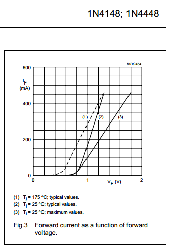
With reference to your forward voltage drop graph and with the voltage protection circuit, the minimum current through the diode is 0 mA and maximum current through the diode is 0.255mA when VIN is 12V. As you can see, with both values you're at the bottom of the graph and the voltage drop is relatively constant (approx 0.6V).
Hi dlloyd, I had the presumption to have a decent understanding of diodes, but apparently I haven't
If the diode is going to ground, with VIN raising from 0 to 12 the voltage at D3 and A0 will raise from 0V at 0V up to 0.5V at 12V if I'm using a diode having a forward voltage of 0.8 @ 1A (well, this is an estimate and really depends on the diode characteristics). This will never be enough for a digitalRead to report an HIGH as TTL HIGH voltage is above 2V...
But your schematic reports the diode going into 5V, which means the pins voltage will be the VIN voltage until it reaches approx 6V when the current flowing through the diode (that is the only path where current can flow as the pins are set as input and as such they are high impedance) will force it into conduction. At that point the voltage on the pins will be around 5.5V and it will raise very slowly up to 5.6V (or thereabouts) when it reaches 12V.
Compared to the grounded diode this has the advantage of reducing the current (the potential difference is going to be 7V instead of 12V) at the expense of a non monotone voltage on the pins: it will raise then drop and then raise again.
Using a voltage divider I have the advantage of being able to easily calculate the input voltage being linearly related to my sensing voltage, at the expense of possibly more current drawn from the source (that will depend on equivalent resistance), but this is not the case as our buddy here is only interested into detecting if there is any potential difference on the line.
Now, getting into the voltage protection I don't get it: the diode is forward biased and parallel to the arduino: if I switch the pins into OUTPUT and put them LOW I will have current (under 1mA) getting into the pins but at an higher voltage (in case of the diode circuit) which means I'll be stressing the internal ESD clamping diode.
I'm not protecting the VIN source either as current is allowed to flow from it into the 5V end: I'm relying on the resistor to limit it, not the diode.
By connecting the diode to 5V I see a potential problem: is the 5V source capable of sinking current (even if in very small amounts)?
Sorry for having being long winded, I 'm just trying to make my reasoning clear, which I might have failed to....
I was trying to keep it simple for you. To a first approximation once a diode is conducting that is it forward voltage. In practice there is a slight increase as the current increases but this is totally irrelevant for what we are talking about. It can never reach the 3V3 needed to register as a logic one.
is the 5V source capable of sinking current
It never has to sink current, the excess current is used by the circuit and the 5V rail just supplies slightly less.
I was trying to keep it simple for you. To a first approximation once a diode is conducting that is it forward voltage. In practice there is a slight increase as the current increases but this is totally irrelevant for what we are talking about. It can never reach the 3V3 needed to register as a logic one.
Ok, thanks!
Grumpy_Mike:
is the 5V source capable of sinking current
It never has to sink current, the excess current is used by the circuit and the 5V rail just supplies slightly less.
Ok! I guess I might argue about the excess current potentially being higher than the 5V rail supplied one, but that would just mean there would be less excess current allowed to flow and that might mean the diode will not be forward biased... Ok, I belive i got the picture.
Now, getting into the voltage protection I don't get it: the diode is forward biased and parallel to the arduino: if I switch the pins into OUTPUT and put them LOW I will have current (under 1mA) getting into the pins but at an higher voltage (in case of the diode circuit) which means I'll be stressing the internal ESD clamping diode.
NOTE: The diode in the circuit should be Schottky type, where its voltage drop is between approximately 0.15–0.45 volts.
If you do this and switch the pin LOW, the pin will be sinking less than 0.3mA which is well within the ±20mA rating of the pin.
If you switch the pin HIGH, the schottky diode will limit the voltage to around 5.2V, so the internal clamping diode will never conduct. Actually, even if the schottky diode was removed, 0.3mA through the internal clamping diode would not be enough to stress it.
Voltage Protection Circuit
offers higher level of protection.
ideal for detecting "presence" of voltage.
the circuit shown will allow "measuring" any voltage from 0-5V, anything greater gets clamped.
Voltage Divider Circuit
provides voltage level translation.
ideal for measuring a scaled down version of a bigger signal.
allows for full range measurement of the input.
ideal for creating a reference voltage when powered by a regulated source.
Unfortunately, poor ol' Mike appears to have completely befuddled you with an "out-field" remark whose intent I simply cannot understand:
Grumpy_Mike:
Vcc should be ground.
I have no idea what Mike meant by this "throw-away" line, and not sure if he does either!
Please get this absolutely clear - the diode goes to Vcc as dlloyd illustrates. It conducts if the voltage supplied to the resistor goes above the 5V Vcc and limits the voltage to the Arduino to the diode drop above Vcc. With the 47k resistor, the system is safe to 12V or (a fair degree more) even without the diode as you would have to apply more than 52V to pass more than 1 mA.
If there is a concern about the input voltage going negative, then another diode can go to ground with the diode in the opposite direction so that it conducts if and when the voltage goes negative.
And incidentally, the behaviour of CMOS is that if the pin happened to be set as an output, then the output driver (even when HIGH) would sink current and substantially restrict the pin voltage from rising above Vcc as well.
Again, if all you need is to determine whether the 12V is present or not, then you do not need to use an analog input.