Arduino noob here!
I have been trying to find the best way to read a high resolution rotary encoder (I am using a SCANCON SCH50B with 12500ppr with an Arduino Uno). The encoder is attached to the shaft of a motor rotating at ~1Hz.
I have been looking around at codes and trying different methods and the best explanation I found so far is on a makeatronics blog post
edit: link not working for some reason. here it is
I have tried codes using pins-read functions and register-read functions but they don't seem to do the job good enough.
Interrupts, on the other hand, seem to work (as in the link - I re-post the code down here).
The question is: how do I know the works efficiently enough? Do I ever miss encoder steps? How do I evaluate the limitations of interrupts given my specific application? I feel I miss some basic knowledge on limitations of arduino hardware and interrups.
Additional question: what is the best way to save the data coming from those interrups? (e.g. from the code below I would like to save enc_count to a csv file for later use). This should also contain some timestamp of sorts
volatile long enc_count = 0;

void setup() {
    // all your normal setup code
    attachInterrupt(0,encoder_isr,CHANGE);
    attachInterrupt(1,encoder_isr,CHANGE);
    Serial.begin(1000000);

}

void loop() {
      // Serial.println(enc_count);    SHOULD THE PRINT GO HERE?
}

void encoder_isr() {
    static int8_t lookup_table[] = {0,-1,1,0,1,0,0,-1,-1,0,0,1,0,1,-1,0};
    static uint8_t enc_val = 0;

    enc_val = enc_val << 2;
    enc_val = enc_val | ((PIND & 0b1100) >> 2);

    enc_count = enc_count + lookup_table[enc_val & 0b1111];
 // Serial.println(enc_count);    SHOULD THE PRINT GO HERE?
}
rotating at 1 Hz means 12500 pulses per second.
That is - If the pulse has a duty-cycle of 50% this means every 80 microseconds another pulse
On rotary-encoders the signals of the two channels have a shift of 90 degree to each other.
So the next pulse of the other channel can occur after 20 microseconds. To be sure over all this means
your ISR-executiontime has to be shorter than 20 microseconds.
ISR-s should run as fast as possible. So inside the ISR only the real nescessary things are done.
Anything else is done outside the isr.
A serial output even at a speed of 2.000.000 Baud needs 4 microseconds per character
1/2.000.000 * 8 bit = 4 µsecs
So the serialoutput should be done outside.
inside the isr just store the value into an array.
A good solution depends on how often you want to measure the counted pulses.
For some hundreds you could store them all into an array and after finishing measuring
sending all array-values over serial interface.
If you wish to continually counting the pusles it depends on how fast the values can be sended over serial-interface
in comparing to how fast new values accumulate.
I don't know if serial-output can run at high speed (=high baudrate) in parallel with two ISR which get triggered that fast and often.
Just a quick note... why are you calling this method/Function "encoder_isr()". As far as I understand, an ISR route is used in the case of
an unexpected problem occurring during executing program
Interrupt Service Routine is a function attached to a particular interrupt. Its called whenever the
interrupt triggers, interrupting the main flow of the program, then resuming it seamlessly.
There are things you need to know if coding ISR's about using volatile and critical sections.
You'll find various encoder libraries that do the work for you.
My way of seeing how much time an ISR is using is to attach an oscilloscope to a spare pin
and have the ISR toggle that pin on entering and exiting.
Thank you Stefan and MarkT for the help in understanding.
Stefan's explanation was enlightening and I think I now trust that I am not losing steps along the way.
It remains the doubt about saving data.
I think I need at least 15000 points to be saved in order to test and play with the system.
Those can be saved after the motion, but then I need memory. I will try to google around and play with this idea.
If any other idea or thought comes to mind I would be very grateful!
Thanks!
Lorenzo
TomGeorge:
Hi,
Can you tell us your project and why you need such a high resolution encoder?
Thanks.. Tom..
Hi Tom!
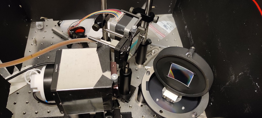
I am trying to build a cheap-but-highRes monochromator. I have a motor moving a holographic grating back and forth to split the color of a light source. The split colors illuminate a fine aperture (thus you get only one color output for each angle of the motor). The wavelength (or color) information at the output can be measured by knowing where the motor is at all times. For this reason I use a fancy encoder - the necessary resolution is very high.
Thus, I need to read the many pulses and be sure that I do not miss steps.
After a scanning of colors, I need the timestamps/positions in order to calculate the color at the output as a function of time/position.
Here is a pictures of a prototype because reasons!
Wow pretty high-tech-parts.
As you need such a high resolution to determine the exact position
what mechanical parts are moving? I took a close look at the picture but I don't understand how the parts move.
Whenever there is more than direct rotation of the stepper-motor I guess linearity deviation of the parts have to be examined too. For example even high-quality ballscrew-spindels do have a linearity deviation along the thread.
15000 readings is too much for an Arduino Uno to store at once
For example an ESP32 has 256kB SRAM and runs at 160 or 240 MHz. But I'm not sure if an ESP32 is best suited for this application.
I did a RAM-usage-test with this code that has an array of 16.000 unsigned longs
#define MaxElements 16000

unsigned long MyArray[MaxElements];
unsigned long n;
unsigned long myDummy;

void setup() {
    myDummy = 0;
    Serial.begin(115200);
    for (n = 0; n < MaxElements; n++) {
        //delay(10);
        MyArray[n] = random(0,255);
        Serial.println(MyArray[n] - 50);
    }
}
void loop() {
    myDummy = random(0,MaxElements - 1);
    MyArray[myDummy] = random(0,255);

    for (n = 0; n < MaxElements; n++) {
        delay(10);
        Serial.println(MyArray[n]);
    }
}
the random is needed to force the compiler to not optimize away the huge RAM-usage.
the compiler reports
"C:\\Users\\Stefan\\AppData\\Local\\Arduino15\\packages\\esp32\\tools\\xtensa-esp32-elf-gcc\\1.22.0-80-g6c4433a-5.2.0/bin/xtensa-esp32-elf-size" -A "C:\\Users\\Stefan\\AppData\\Local\\Temp\\arduino_build_287021/Test-Ram-usage-002.ino.elf"
Sketch uses 213457 bytes (16%) of program storage space. Maximum is 1310720 bytes.
Global variables use 79372 bytes (24%) of dynamic memory, leaving 248308 bytes for local variables. Maximum is 327680 bytes.
StefanL38:
Wow pretty high-tech-parts.
As you need such a high resolution to determine the exact position
what mechanical parts are moving? I took a close look at the picture but I don't understand how the parts move.
Whenever there is more than direct rotation of the stepper-motor I guess linearity deviation of the parts have to be examined too. For example even high-quality ballscrew-spindels do have a linearity deviation along the thread.
15000 readings is too much for an Arduino Uno to store at once
For example an ESP32 has 256kB SRAM and runs at 160 or 240 MHz. But I'm not sure if an ESP32 is best suited for this application.
I did a RAM-usage-test with this code that has an array of 16.000 unsigned longs
#define MaxElements 16000
unsigned long MyArray[MaxElements];
unsigned long n;
unsigned long myDummy;
for (n = 0; n < MaxElements; n++) {
delay(10);
Serial.println(MyArray[n]);
}
}
the random is needed to force the compiler to not optimize away the huge RAM-usage.
the compiler reports
"C:\Users\Stefan\AppData\Local\Arduino15\packages\esp32\tools\xtensa-esp32-elf-gcc\1.22.0-80-g6c4433a-5.2.0/bin/xtensa-esp32-elf-size" -A "C:\Users\Stefan\AppData\Local\Temp\arduino_build_287021/Test-Ram-usage-002.ino.elf"
Sketch uses 213457 bytes (16%) of program storage space. Maximum is 1310720 bytes.
Global variables use 79372 bytes (24%) of dynamic memory, leaving 248308 bytes for local variables. Maximum is 327680 bytes.
best regards Stefan
Thanks Stefan!
I have tried to use an array and store there (using a similar code as what I posted) and the maximum that works is [450]. Above that it does not compile for lack of memory.
At the moment I am testing using the serial print in the loop and then connecting hooking up matlab to the serial and I see OK data. Of course I cannot be sure I am getting all the points (since the loop will be interrupted when an interrupt occurs) but what I get is at least correct, which is nice.
regarding the movement, I use a stepper motor with some fancy drivers to do microstepping to a high degree, making the motion very smooth. In the picture the motor is below the grating so not really visible. That is the only moving part.
Of course mechanics and linearity of movement play a huge role, but if the position sensing is precise enough, I can compensate once I get the data (doing some interpolation to obtain a wavelength axis with even spacing between points), so that is solved at least.
-Lorenzo
I'd forget about using an Uno for this project. If you use at least a Teensy 3.2 and the GitHub encoder library I referenced in Reply #5 of this forum thread, , you'll have no problem keeping up with the rotation rate / resolution that you're trying to get. Note that the Teensy 3.x family is 3.3V logic, so you need to supply that to the encoder also, not 5V.
You might need to go with a Teensy 3.5 or 3.6 for sufficient RAM if you really need to store all those data points. These boards have a built-in micro-SD card socket, so you could also transfer the data to the card and then to a PC.
another idea:
if you use another microcontroller that has enough RAM for all points
you could setup another interrupt that is timer-driven to store snapshots of the counter-variable
every delta-t where delta-t is constant.
increasing a index-variabe by 1 and storing a value into an array-element should be executed very fast.
this command does increase the index-variable and store the value of pulsecounter by just one line.
I'm not sure if understand the whole process right. By turning some parts with the steppermotor a lightbeam with a very small wavelength-band is created and I guess some light-sensor will be triggered if the wavelength is reflected or absorbed somewhere. With this triggering the wave-length can be calculated based on the rotating-angle.
So whenever the light-sensor is triggered a snapshot of the encoder-pulse-counter should be made.
So for each intensity-spike the pulse-counter-value is stored.
Is this a correct description of what is going on?
or is it that way
A lightsensor gives a higher or lower analog signal depending on the wavelength of the created monchrome light. Now the correlation between wave-length and sensor-signal is of interest.
This way storing the light-sensor-signal every delta-phi of angle is interesting.
This would mean the encoder-pulse increases the array-index and the array-element stores the light-sensor-signal.
Thank you guys for all the help! I am learning a lot.
Regarding the "changing controller" I agree. Maybe I can use an Arduino Mega instead of a Teensy?
To answer Stefan: a monochromator is basically a color filter. You have a white light on one side, which shines on a grating. This grating is just like the back of a CD, it splits colors in a rainbow. So if you rotate the grating you get different colors at the output. So a different point in the motion of the motor corresponds to a different color at the output, and I need to know exactly what color I have in every time unit.
This means high precision requirement for the position readout and also the need for a timestamp.
Is there a way using a Mega to get the position and the relative timestamp all in one interrupt?
I think the Mega has an "absolute clock" I could use, doesn't it?
Thanks again,
Lorenzo
have a look at the Ardunio Due which uses a AT91SAM3X8E which has a hardware quadrature decoder, see section 36. Timer Counter (TC) of datasheet The TC embeds a quadrature decoder (QDEC) connected in front of the timers and driven by TIOA0, TIOB0 and TIOB1 inputs. When enabled, the QDEC performs the input lines filtering, decoding of quadrature signals and connects to the timers/counters in order to read the position and speed of the motor through the user interface
horace:
have a look at the Ardunio Due which uses a AT91SAM3X8E which has a hardware quadrature decoder, see section 36.
That's another good idea. The NXP (nee freescale) processors used on the Teensy 3.x boards have the same capability. Personally, I find their datasheets to be a little bit better than Atmel's. But, either of them could work.
I have not used the QEI hardware decoder on the Arduino Due but have on a PIC24EP256MC206 and dsPIC microcontrollers and it is the answer for measuring high speed rotation where even GPIO interrupt on change may not cope